Often when you are working on a project, you will find that parts of the code pretty much repeat over and over, and life would be so much easier, if you could just combine all that code into one neat little package.
Normally this is not that hard, you just use a function, but when you start mixing in LVGL widgets it can be hard to keep in control of everything and simplify at the same time. That is why today I will show you an example on how to simplify your LVGL code.
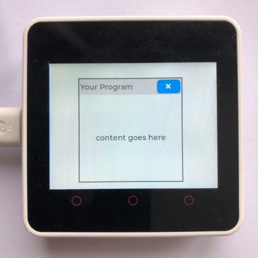
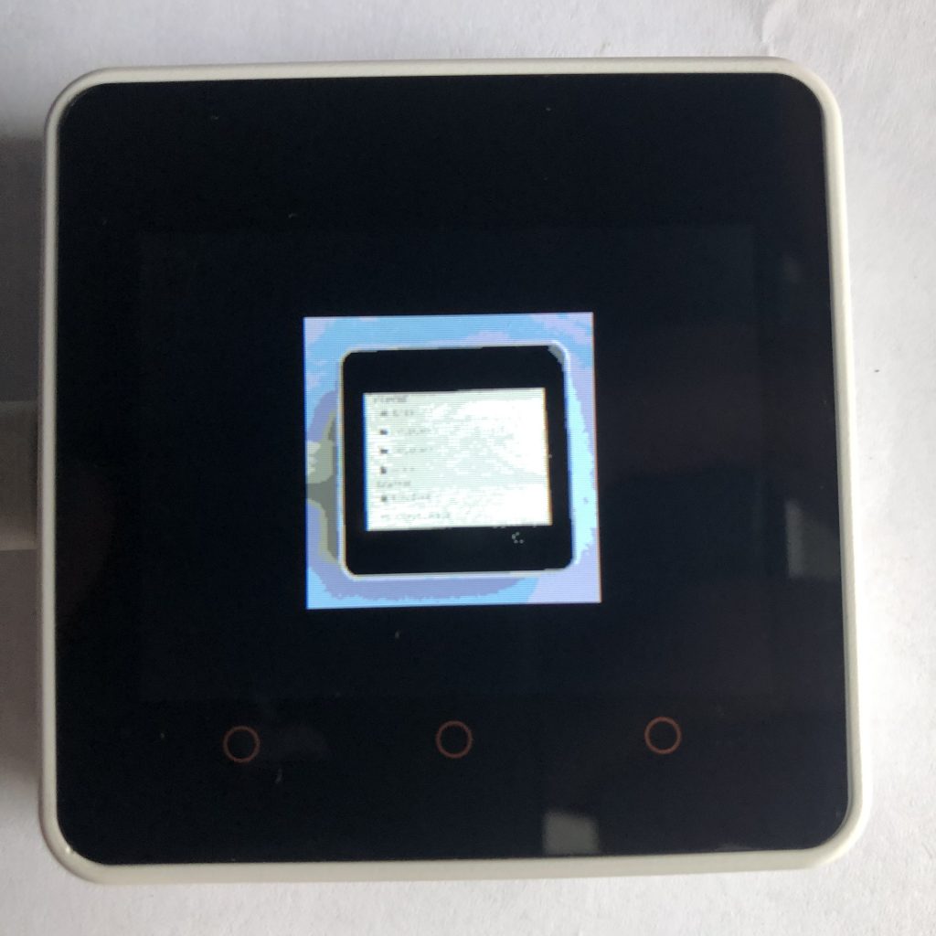
Setting Up a Micropython Screen
Obviously, if you are creating a program that uses LVGL, you have to have access to a screen.
Because there are so many different screens out there, I can’t add support for all of them, so to make this example work, you will need to add your screen’s setup code to the beginning of this example.
There is a little more information on this process at How to get a LVGL Micropython Screen to Work if you aren’t familiar on how it’s done.
here is the example code.
import lvgl
def Dropdown(name,final_size,scr):
container = lvgl.obj(scr)
container.set_size(300,40)
container.set_pos(5,5)
container.set_style_radius(15,0)
container.set_style_pad_all(0,0)
container.set_scrollbar_mode(lvgl.SCROLLBAR_MODE.OFF)
label1 = lvgl.label(container)
label1.set_text(name)
label1.set_pos(10,10)
sw1 = lvgl.switch(container)
sw1.set_size(60,30)
sw1.set_pos(230,4)
line = lvgl.line(container)
line.set_pos(0,40)
points = [{"x":5,"y":0},{"x":290,"y":0}]
line.set_points(points,2)
line.set_style_line_color(lvgl.color_hex(0xDDDDDD),0)
down = lvgl.anim_t()
down.init()
down.set_var(container)
down.set_time(300)
down.set_values(40,final_size)
down.set_custom_exec_cb(lambda not_used,value : container.set_height( value))
up = lvgl.anim_t()
up.init()
up.set_var(container)
up.set_time( 300 )
up.set_values( final_size, 40 )
up.set_custom_exec_cb( lambda not_used, value : container.set_height( value ))
sandbox = lvgl.obj(container)
sandbox.set_pos(5,35)
sandbox.add_flag(lvgl.obj.FLAG.HIDDEN)
sandbox.set_size(290,final_size-40)
sandbox.set_style_border_side(lvgl.BORDER_SIDE.NONE,0)
def switch_clicked(data):
switch = data.get_target()
state = switch.has_state(lvgl.STATE.CHECKED)
print(state)
if state:
down.start()
sandbox.clear_flag(lvgl.obj.FLAG.HIDDEN)
line.clear_flag(lvgl.obj.FLAG.HIDDEN)
else:
up.start()
sandbox.add_flag(lvgl.obj.FLAG.HIDDEN)
line.add_flag(lvgl.obj.FLAG.HIDDEN)
sw1.add_event_cb(switch_clicked,lvgl.EVENT.CLICKED,None)
return (container,sandbox)
Container,Sandbox = Dropdown("Something To Control",150,lvgl.scr_act())
Container.set_pos(10,10)
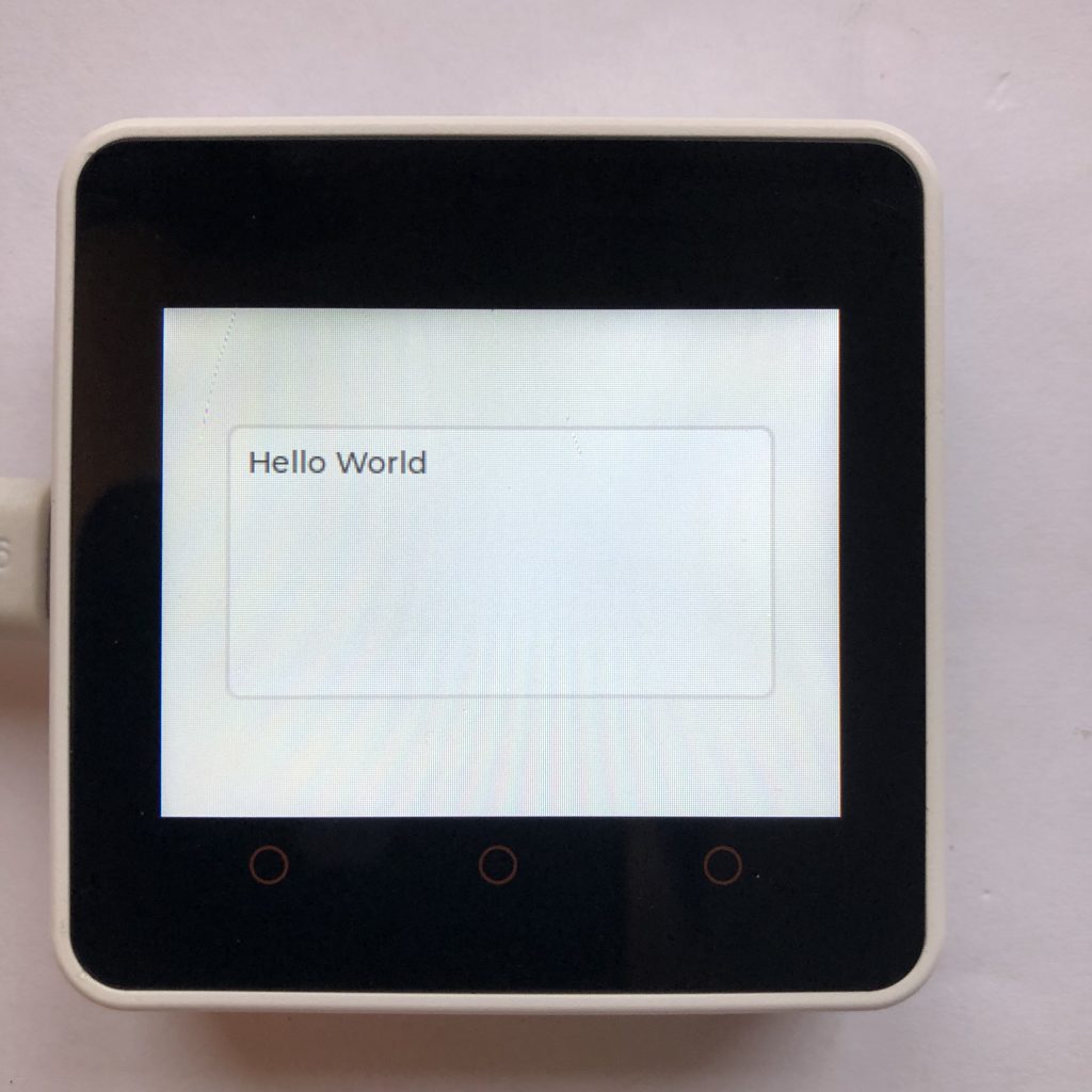
Some_Text = lvgl.label(Sandbox)
Some_Text.set_text("Controls for it")
Some_Text.center()Understanding This LVGL Code
Ok, now that you have seen all the code, let’s step through each section, so you can understand the basic tricks to making you code simpler.
Using a Function
As mentioned before, Functions are a great start to making code smaller, so our example code begins by creating one. We will call this function Dropdown and make it take three arguments.
def Dropdown(name,final_size,scr):A Container
The next big trick is to create a LVGL object. Later when we start creating more LVGL objects, we will always put them inside of this first object.
This will dramatically simplify group actions, like if you want to move every object 10 pixels to the left, all you have to do is move the container 10 pixels, and everything inside of it will move ten pixels as well.
container = lvgl.obj(scr)After that, we will set some settings like the size of the the container, it’s position, and how rounded the corners should be.
    container.set_size(300,40)
    container.set_pos(5,5)
    container.set_style_radius(15,0)
LVGL’s default padding is just a little to much for the size of my screen, so I removed it like this.
container.set_style_pad_all(0,0)Next we can remove the scrollbar. Because we will use animations later, there will be a small amount of time where the content is to large for our container. LVGL by default will try to add a scrollbar when that happens, which totally ruins how everything looks for a few seconds.
container.set_scrollbar_mode(lvgl.SCROLLBAR_MODE.OFF)Some Content
After that we will add a little content inside of our main object. This is all pretty standard stuff, so I will not bore you with the details.
    label1 = lvgl.label(container)
    label1.set_text(name)
    label1.set_pos(10,10)

    sw1 = lvgl.switch(container)
    sw1.set_size(60,30)
    sw1.set_pos(230,4)

    line = lvgl.line(container)
    line.set_pos(0,40)
    points = [{"x":5,"y":0},{"x":290,"y":0}]
    line.set_points(points,2)
    line.set_style_line_color(lvgl.color_hex(0xDDDDDD),0)
Animations
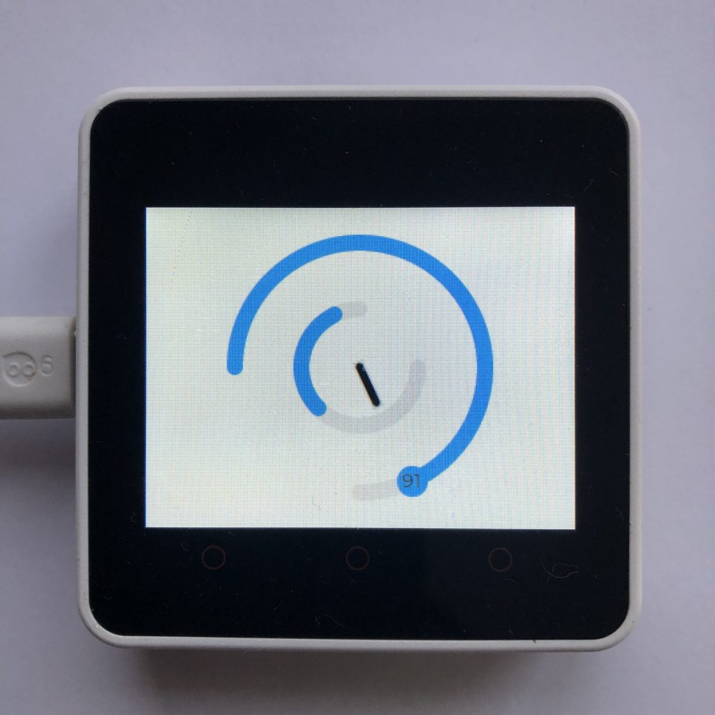
We are going to use animations to smoothly change the size of are custom widget. Animations are complex and really out of the scope of this post, so I will not explain them here. If you are not very familiar with animations, you might be interested in seeing some simple Animation Examples.
    down = lvgl.anim_t()
    down.init()
    down.set_var(container)
    down.set_time(300)
    down.set_values(40,final_size)

    down.set_custom_exec_cb(lambda not_used,value : container.set_height( value))

    up = lvgl.anim_t()
    up.init()
    up.set_var(container)
    up.set_time( 300 )
    up.set_values( final_size, 40 )
import lvgl
    up.set_custom_exec_cb( lambda not_used, value : container.set_height( value ))
Another Container
Next we are going to create another container. We will use it later as a sandbox, just a little area were you can add anything you want to it.
    sandbox = lvgl.obj(container)
    sandbox.set_pos(5,35)
    sandbox.add_flag(lvgl.obj.FLAG.HIDDEN)
    sandbox.set_size(290,final_size-40)
    sandbox.set_style_border_side(lvgl.BORDER_SIDE.NONE,0)
Creating Some Action
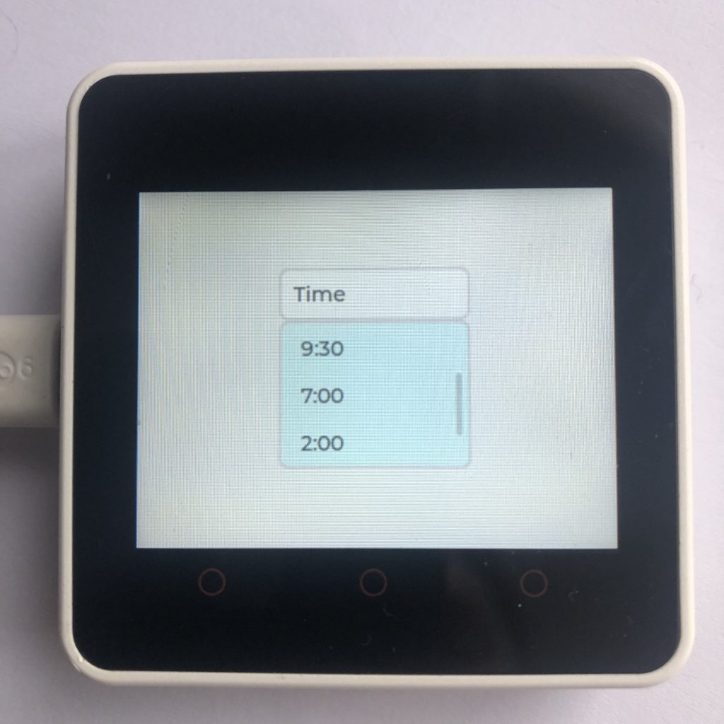
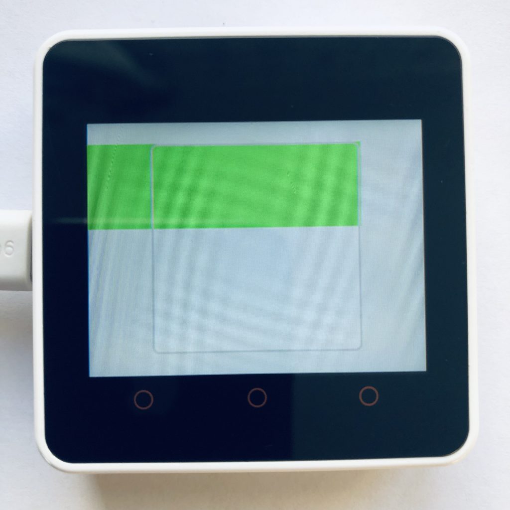
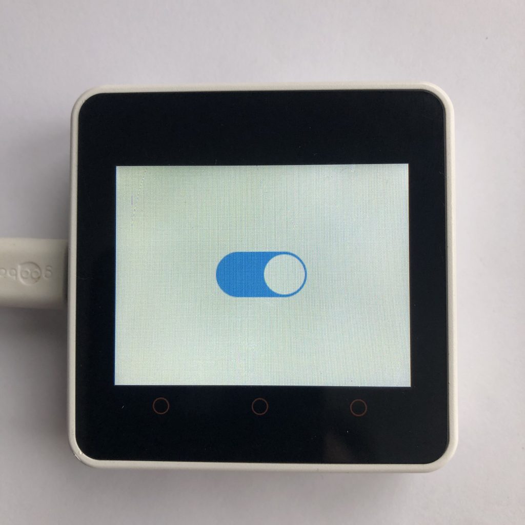
Up to this point, we have created a bunch of basic widgets. Now what we are going to do is add an event handler. We kind of skipped over it, but earlier we created a switch, what we want to happen now is when ever that switch is turned on the hole container get larger and an extra section pops out.
Whenever we need to respond to some action in LVGL, we use handlers, so lets create one.
def switch_clicked(data): The first thing we do in this handler function, will be to check if the switch is on or off.
switch = data.get_target()
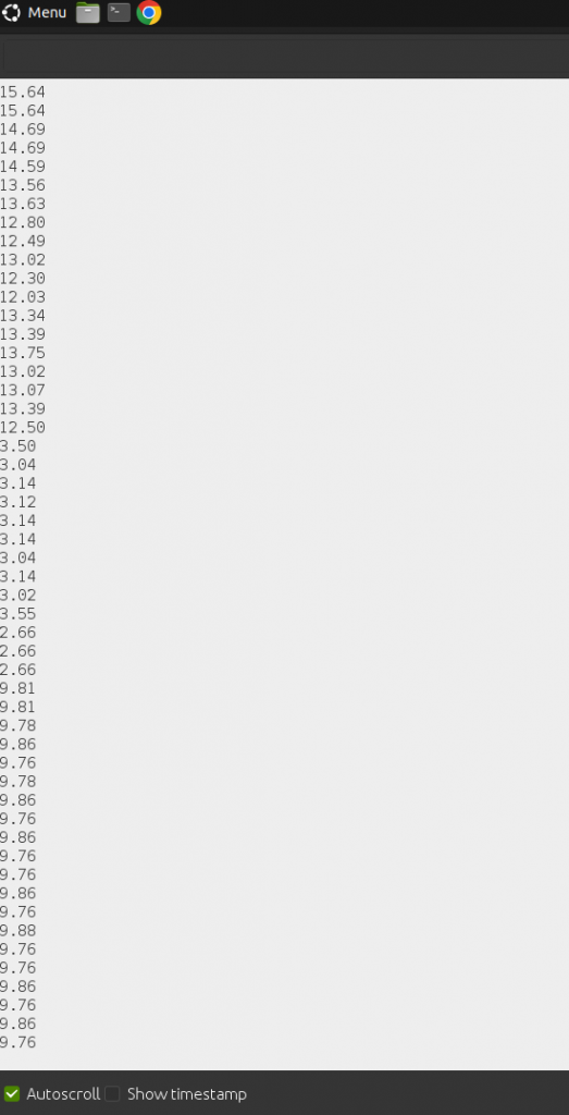
state = switch.has_state(lvgl.STATE.CHECKED)Then we will print that answer to the terminal.
print(state)After that, we will create an if statement to respond to the current state.
        if state:
            down.start()
            sandbox.clear_flag(lvgl.obj.FLAG.HIDDEN)
            line.clear_flag(lvgl.obj.FLAG.HIDDEN)
        else:
            up.start()
            sandbox.add_flag(lvgl.obj.FLAG.HIDDEN)
            line.add_flag(lvgl.obj.FLAG.HIDDEN)
While the if statement is pretty simple, the code inside of it is less so. Here is what it does.
First if the switch has been turned on, it will start the down animation we created earlier. All that animations does is change the height of our sandbox container to 150px.
down.start()Then, it makes all of the stuff inside that container not hidden aka visible.
            sandbox.clear_flag(lvgl.obj.FLAG.HIDDEN)
            line.clear_flag(lvgl.obj.FLAG.HIDDEN)
And if the Switch was turned off, it does the opposite. It shrinks the container to 40 pixels tall and hides the stuff inside of the container.
            up.start()
            sandbox.add_flag(lvgl.obj.FLAG.HIDDEN)
            line.add_flag(lvgl.obj.FLAG.HIDDEN)
Convenience
This last line of code is really short, but also really important.
return (container,sandbox)What it does is return both the main container and the smaller one inside it. Take note of the parenthesizes and coma, they condense multiple items into one item, so we can use it as the return value of our function.
Passing the main container is useful, because it easily allows us to move everything around the screen, and passing the second container is useful ,because it allows us to quickly edit what we want.
Using Our Function
Now that we have created our function lets use it. Because this function returns multiple variables when it ends, we will use a trick called unpacking to get all of them available as quickly as possible.
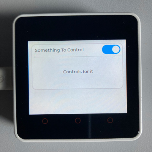
Container,Sandbox = Dropdown("Something To Control",150,lvgl.scr_act())Now we have two variables: Container and Sandbox. We will start out by moving the Container, when we move it, everything we have created will move with it as well.
Container.set_pos(10,10)We made the Sandbox variable to be a little area that will occasionally pop out. If we create something inside of it, when Sandbox appears so will what ever we created.
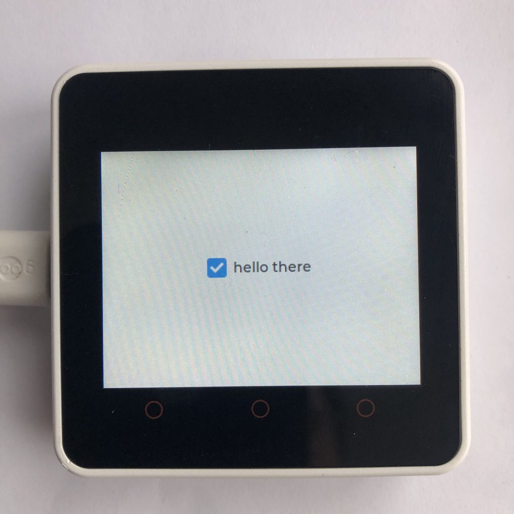
Lets create a basic label and center it inside of our Sandbox.
Some_Text = lvgl.label(Sandbox)
Some_Text.set_text("Controls for it")
Some_Text.center()
What Next?
This example creates a relatively unique widget, so I would suggest first of all just running the code and seeing what it creates. Then start playing around with it. While this example is a bit long, that is mostly because I went a bit overboard with the animations and styles. The basic principles here are actually very simple.
- First, you put your code inside of a function.
- Second, you create an LVGL object, which all further objects are put inside of.
- Third, you return all important LVGL objects from the function using tuples and unpacking.
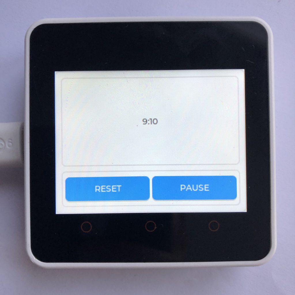
If you found this tutorial interesting you might like to see a complete LVGL Timer App Example.