Baxter Builds

FreeRTOS Mutex Example

May 19, 2023 by Baxter

the esp32 that I run the code on

Mutexes can be one of the harder parts of FreeRTOS to learn. They are slower than semaphores, but don’t seem to do anything special. I am sure you have probably looked up what the difference is and heard about things like Priority inversion and Priority inheritance.

But it is always nice when working through computer theory, to have a simple example that really shows what you are trying to learn, so I have created the following code that shows the basics of how and why you use a mutex in FreeRTOS.

Here is the code

#define LED 16

SemaphoreHandle_t GuardSerial;


void low_priority(void* args) {
  while (true) {
    xSemaphoreTake(GuardSerial, portMAX_DELAY);
    for (int i = 0; i < 200 ; i++) {
      Serial.print("L-");
    }
    Serial.println();
    xSemaphoreGive(GuardSerial);
    delay(500);
  }
}


void medium_priority(void* args) {
  pinMode(LED, OUTPUT);
  while (true) {
    for (int i = 0; i < 10000 ; i++) {
      int k = sin(random(0, 1));
      k += random(0, 20);
      k -= random(0, 10);
      k -= cos(random(0, 1));
      k *= tan(random(0, 1));
      //just waist some time
    }
    digitalWrite(LED, !digitalRead(LED));
    delay(100);
  }
}

void high_priority(void* args) {
  while (true) {
    xSemaphoreTake(GuardSerial, portMAX_DELAY);
    Serial.print("*******high_priority task testing mutexes*******\n");
    xSemaphoreGive(GuardSerial);
    delay(500);
  }
}


void setup() {
  Serial.begin(9600);

  // GuardSerial = xSemaphoreCreateBinary();
  GuardSerial = xSemaphoreCreateMutex();

  xTaskCreate(low_priority, "LOW", 2048, NULL, 1, NULL);

  xTaskCreate(medium_priority, "MID1", 2048, NULL, 2, NULL);
  xTaskCreate(medium_priority, "MID2", 2048, NULL, 2, NULL);
  xTaskCreate(medium_priority, "MID3", 2048, NULL, 2, NULL);
  xTaskCreate(medium_priority, "MID4", 2048, NULL, 2, NULL);

  xTaskCreate(high_priority, "HIGH", 2048, NULL, 3, NULL);
}

void loop() {
}

Understanding this Code

Now that you have seen this example, lets go through each section and see how it works.

The LED

Part of this example is going to use an LED, so to start, we need to define which pin it is connected to.

#define LED 16

Mutex vs Semaphore

A mutex is just a binary semaphore with some added safety measures. Because of this, they are slightly slower than semaphores, but much more reliable (more on this later).

To be able to access a mutex, we will need to create a handler for it, and because mutexes are related to semaphores, we will use the standard semaphore handler like this.

SemaphoreHandle_t GuardSerial;

The Low Priority Task

This example uses three tasks, so lets start working on the first task. We will begin it like most task functions with an infinite loop and a delay.

void low_priority(void* args) {
  while (true) {

    delay(500);
  }
}

Then we will add in some code that prints “L-” 200 times to the Serial port.

void low_priority(void* args) {
  while (true) {
    for (int i = 0; i < 200 ; i++) {
      Serial.print("L-");
    }
    Serial.println();
    delay(500);
  }
}

For this example, we are using mutexes to guard the Serial port, so before we use the Serial port to print “L-” 200 times, we need to get permission from the mutex with the xSemaphoreTake() function.

That function requires two arguments the first one is the semaphore or mutex we want permission from and the second one is the maximum time we should wait for permission before giving up. portMAX_DELAY = forever

void low_priority(void* args) {
  while (true) {
    xSemaphoreTake(GuardSerial, portMAX_DELAY);
    for (int i = 0; i < 200 ; i++) {
      Serial.print("L-");
    }
    Serial.println();
    delay(500);
  }
}

And when we are done with the Serial port we need to release it, so the other tasks can use it with the xSemaphoreGive() function.

void low_priority(void* args) {
  while (true) {
    xSemaphoreTake(GuardSerial, portMAX_DELAY);
    for (int i = 0; i < 200 ; i++) {
      Serial.print("L-");
    }
    Serial.println();
    xSemaphoreGive(GuardSerial);
    delay(500);
  }
}

The Middle Task

This next task doesn’t actually use mutexes, instead its only job is to waist computer power and blink an LED. Later, we will use it to show why mutexes are better than binary semaphores.

void medium_priority(void* args) {
  pinMode(LED, OUTPUT);
  while (true) {
    for (int i = 0; i < 10000 ; i++) {
      int k = sin(random(0, 1));
      k += random(0, 20);
      k -= random(0, 10);
      k -= cos(random(0, 1));
      k *= tan(random(0, 1));
      //just waist some time
    }
    digitalWrite(LED, !digitalRead(LED));
    delay(100);
  }
}

The High Priority Task

This last task is the simplest of the bunch. All it does is get permission from the mutex, send data through the Serial port, release the mutex, and finally wait a while before doing it all over again.

void high_priority(void* args) {
  while (true) {
    xSemaphoreTake(GuardSerial, portMAX_DELAY);
    Serial.print("*******high_priority task testing mutexes*******\n");
    xSemaphoreGive(GuardSerial);
    delay(500);
  }
}

Wrapping it all Together

Up to this point, we have only created some task functions, now we need to turn them into real tasks. We will do all of this and a few other things in the setup() function. Here is what it starts out like.

void setup() {
  Serial.begin(9600);


}

The first thing we will do is create a new mutex and then update the semaphore handler we created earlier to hold it.

void setup() {
  Serial.begin(9600);

  // GuardSerial = xSemaphoreCreateBinary();
  GuardSerial = xSemaphoreCreateMutex();

}

Above you may have noticed that one line of code is commented out. If you uncommit it and commit out the line that comes after it, the program will use a binary semaphore instead of a mutex.

The next thing we will do is create the low priority task, and if you were wondering, we will create it with a priority of one.

void setup() {
  Serial.begin(9600);

  // GuardSerial = xSemaphoreCreateBinary();
  GuardSerial = xSemaphoreCreateMutex();

  xTaskCreate(low_priority, "LOW", 2048, NULL, 1, NULL);

}

After that, we will create four medium priority tasks. We need four of them to just make sure the computer is always running at least one on each core.

void setup() {
  Serial.begin(9600);

  // GuardSerial = xSemaphoreCreateBinary();
  GuardSerial = xSemaphoreCreateMutex();

  xTaskCreate(low_priority, "LOW", 2048, NULL, 1, NULL);

  xTaskCreate(medium_priority, "MID1", 2048, NULL, 2, NULL);
  xTaskCreate(medium_priority, "MID2", 2048, NULL, 2, NULL);
  xTaskCreate(medium_priority, "MID3", 2048, NULL, 2, NULL);
  xTaskCreate(medium_priority, "MID4", 2048, NULL, 2, NULL);
}

And lastly we will create the high priority task.

void setup() {
  Serial.begin(9600);

  // GuardSerial = xSemaphoreCreateBinary();
  GuardSerial = xSemaphoreCreateMutex();

  xTaskCreate(low_priority, "LOW", 2048, NULL, 1, NULL);

  xTaskCreate(medium_priority, "MID1", 2048, NULL, 2, NULL);
  xTaskCreate(medium_priority, "MID2", 2048, NULL, 2, NULL);
  xTaskCreate(medium_priority, "MID3", 2048, NULL, 2, NULL);
  xTaskCreate(medium_priority, "MID4", 2048, NULL, 2, NULL);

  xTaskCreate(high_priority, "HIGH", 2048, NULL, 3, NULL);
}

Why Use Mutexes

When we started, I said I would show you how and why to use a mutex. We have seen the how, now lets look at the why.

In this example at line 48, there is some code that is commented out.

// GuardSerial = xSemaphoreCreateBinary();
GuardSerial = xSemaphoreCreateMutex();

If you uncommit the first line and commit out the second line, the example will use a binary semaphore instead of a mutex.

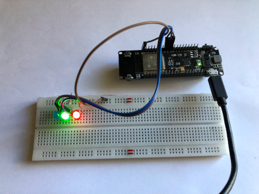
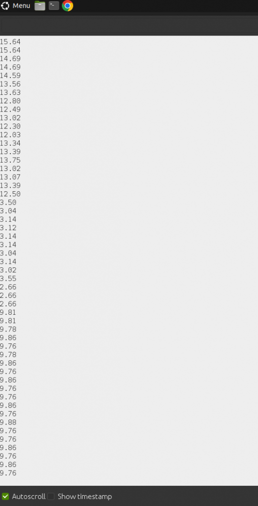
Try running it, if you do you will see something a little strange happening, or more accurately you will see nothing happening in the Serial Monitor, but the led will keep blinking.

What this means is that the low and high priority tasks have been halted, and only the medium priority task is running which is not what we want. The high priority task should always be run first, and that is what mutexes are for, they guarantee that your high priority tasks get run as soon as possible.

Mutexes can do a lot but not every thing. There are still a few things that semaphores are better at, and if you want to learn a little more about them, you might like to see a semaphore example.

Filed Under: Arduino, FreeRTOS

FreeRTOS Task Notification Example

May 9, 2023 by Baxter

the esp32 board I use with "notifications" written above it

FreeRTOS has many conventional tools like semaphores and queues available to it, but it also has an extremely powerful unconventional tool as well, notifications.

Notifications were designed as a low level way to synchronize tasks. because of that, they are very fast and allow you to synchronize tasks in a lot of different ways.

There are two interfaces that you can use with notifications, so below I have prepared two simple examples about how to use each.

Here is the first example

TaskHandle_t address = NULL;


void send(void* arg){
 while(true){
  xTaskNotifyGive(address);
  delay(800);
 }
}

void receive(void* arg){
  while(true){
    ulTaskNotifyTake(true,portMAX_DELAY);
    Serial.println("GOT MESSAGE");
  }
}


void setup() {
  Serial.begin(115200);

  xTaskCreate(receive,"RECEIVE",2048,NULL,1,&address);
  xTaskCreate(send,"SEND",2048,NULL,1,NULL);
}


void loop() {
}

How It Works

This example uses the simpler interface which I prefer, so we will start with it. Why don’t we quickly go through it and see how it works.

The Address

One of the big differences between Notifications and Semaphores, Mutexes, etc. is that when you send a notification you have to tell it the address of the task you are sending it to.

This address is actually the handler of the task, so for now we need to create a variable to hold that address like this.

TaskHandle_t address = NULL;

Of course, we can’t actually set the address until we create the task, so we will have to wait for now.

The Sender Function

Next, we are going to create a function for the task that sends the notifications, and we will start it with an infinite loop and a delay.

void send(void* arg){
 while(true){

  delay(800);
 }
}

The actual line of code that send the notification is also pretty simple.

void send(void* arg){
 while(true){
  xTaskNotifyGive(address);
  delay(800);
 }
}

Receiving Notifications

The receiver task also starts out pretty simple.

void receive(void* arg){
  while(true){
 
  }
}

Then, we use the xTaskNotifyTake() function to halt the task until it receives a notification. This function takes two arguments, ClearCount and TicksToWait.

TicksToWait is pretty standard, Its just the maximum amount of time the function should wait for a notification, but ClearCount is a little more interesting.

First of all, here is what this command looks like when we add it in. I have also added a Serial.println() function to tell the user when it receives a notification.

void receive(void* arg){
  while(true){
    ulTaskNotifyTake(true,portMAX_DELAY);
    Serial.println("GOT MESSAGE");
  }
}

Now back to ClearCount, above you can see that I set it to true. Here is a quick table that shows you what ClearCount does.

FalseMakes the notification act like a counting semaphore, allows you to GIVE multiple times in a row and then TAKE the same number of GIVES.
TrueMakes the notification act like a binary semaphore, allows you to GIVE multiple times in a row and then TAKE only once

Order Matters

The last thing we need to do is turn those functions into tasks, and we will also need to update the address variable.

The order in which you create the tasks is extremly important. When I was making this code I made the mistake of creating the sender first, but the program kept crashing.

The reason the order matters is that, when you create the sender task it will immediately run, and if the receiver does not exist yet, when it tries to send a notification the whole computer will crash, so you have to create the receiver first.

void setup() {
  Serial.begin(115200);

  xTaskCreate(receive,"RECEIVE",2048,NULL,1,&address);
  xTaskCreate(send,"SEND",2048,NULL,1,NULL);
}

The Second Example

Besides the simple mechanisms above, notifications also have a slightly more complex way to send a message that also has a 32-bit number sent with it, so here is the next example.

TaskHandle_t receiver = NULL;


void send(void* arg){
 while(true){
  unsigned int val = random(0,10);
  Serial.printf("Sending Number: %i \n",val);
  xTaskNotify(receiver,val,eSetValueWithOverwrite);
  delay(800);
 }
}

void receive(void* arg){
  while(true){
    uint32_t msg = 0;
    xTaskNotifyWait(0,0,&msg,portMAX_DELAY);
    Serial.printf("Got Number: %i \n",msg);
  }
}


void setup() {
  Serial.begin(115200);

  xTaskCreate(receive,"RECEIVE",2048,NULL,1,&receiver);
  xTaskCreate(send,"SEND",2048,NULL,1,NULL);
}


void loop() {
}

Because this example is so similar to the last, I will just explain the two areas that have changed.

Sending

The sending code has changed as follows.

unsigned int val = random(0,10);
Serial.printf("Sending Number: %i \n",val);
xTaskNotify(receiver,val,eSetValueWithOverwrite);

This example uses the xTaskNotify() function. The main advantage of using this function is that not only can you send a notification, but you can also directly manipulate the 32-bit number that is sent with it.

Of course to send a number, we first need to create one. For this example, we will just randomly generate one.

unsigned int val = random(0,10);

And then,it sends it with this.

xTaskNotify(receiver,val,eSetValueWithOverwrite);

If you look at the code above you will see eSetValueWithOverwrite, this controls what the notification does with the value. Besides overwrite, there are four other options which you can learn about at the notification documentation.

Receiving

Here is where we changed the receiving code.

uint32_t msg = 0;
xTaskNotifyWait(0,0,&msg,portMAX_DELAY);
Serial.printf("Got Number: %i \n",msg);

The first thing we do is create a variable to hold the incoming value from the notification.

uint32_t msg = 0;

Then, we use the xTaskNotifyWait() function. This function takes four arguments the first two are a bit complicated, so I will let the documentation explain them to you, but you can set them to zero if you don’t care about them.

The last two arguments are really easy, you just pass it the variable we made, so it can set it to the correct value, and after that you pass it the maximum time it should wait for a notification. portMAX_DELAY = forever

Serial.printf("Got Number: %i \n",msg);

The Downside to Notifications

While Notifications are extremely powerful and are a great tool to have around when working with microcontrollers, they have one main downside, complexity.

Admittedly, it’s not that hard to create a single notification, but because you have to store the address of your tasks and then determine which address to use later, It can be very hard to manage a large number of notifications.

If you are interested in some of FreeRTOS’s other powerful protocols, you might like to see how a mutex works.

Filed Under: Arduino, FreeRTOS

FreeRTOS Semaphore Example

May 2, 2023 by Baxter

an ESP32(the board I am using) I with some text above it

Examples are one of the best tools for learning a new library, and FreeRTOS is no exception, so to help you along in your journey of learning FreeRTOS and in particular FreeRTOS Semaphores here is a quick example.

It works by taking two lists of numbers and adding them together. It does this three times the first time with one task doing all the work, the second with two, and the third with five, and to keep all of those tasks in sync, we will use a counting semaphore.

Here is the code

int A[7] = {1, 2, 3, 4, 5, 6, 7};
int B[7] = {4, 7, 3, 8, 2, 2, 9};


SemaphoreHandle_t data_left;


void process(void* arg) {
  while (xSemaphoreTake(data_left, portMAX_DELAY)) {
    unsigned int count = uxSemaphoreGetCount(data_left);
    Serial.printf("%i: %i + %i = %i \n", count, A[count], B[count], A[count] + B[count]);
    delay(500);
  }
  vTaskDelete(NULL);
}


void setup() {
  Serial.begin(115200);
  unsigned int time = millis();

  data_left = xSemaphoreCreateCounting(7, 7);


  Serial.println("Using One Thread");
  xTaskCreate(process, "P-ONE", 2048, NULL, 1, NULL);


  while (uxSemaphoreGetCount(data_left) != 0) delay(100);
  Serial.printf("Time: %i\n", millis() - time);
  time = millis();

  vSemaphoreDelete(data_left);
  data_left = xSemaphoreCreateCounting(7, 7);

  Serial.println("Using Two Threads");
   xTaskCreate(process, "P-TWO", 2048, NULL, 1, NULL);

  while (uxSemaphoreGetCount(data_left) != 0) delay(100);
  Serial.printf("Time: %i\n", millis() - time);
  time = millis();
  
  vSemaphoreDelete(data_left);
  data_left = xSemaphoreCreateCounting(7, 7);

  Serial.println("Using Five Threads");
  xTaskCreate(process, "P-THREE", 2048, NULL, 1, NULL);
  xTaskCreate(process, "P-FOUR", 2048, NULL, 1, NULL);
  xTaskCreate(process, "P-FIVE", 2048, NULL, 1, NULL);


  while (uxSemaphoreGetCount(data_left) != 0) delay(100);
  Serial.printf("Time: %i\n", millis() - time);

}

void loop() {

}

How This Code Works

Now, that you have seen the example code, why don’t we look through the interesting sections of it and see what they do and how they work.

The Numbers

The first thing the program does is create two lists with 7 numbers in each. These will be the numbers we will add together later.

int A[7] = {1, 2, 3, 4, 5, 6, 7};
int B[7] = {4, 7, 3, 8, 2, 2, 9};

Creating The Semaphore Handler

You don’t actually access semaphores directly, instead you have to go through a semaphore handler, so the next thing, we will do, is create one.

SemaphoreHandle_t data_left;

The Task Function

We will start out with a basic task function that we will call process.

void process(void* arg) {


  vTaskDelete(NULL);
}

Next, we are going to add an infinite loop that checks, if there is any data left to process.

void process(void* arg) {
  while (xSemaphoreTake(data_left, portMAX_DELAY)) {

  }
  vTaskDelete(NULL);
}

If there is data to process, we will find the position of the data, process it(aka. add the two numbers together), print the result to Serial, and then delay for 500 milliseconds.

void process(void* arg) {
  while (xSemaphoreTake(data_left, portMAX_DELAY)) {
    unsigned int count = uxSemaphoreGetCount(data_left);
    Serial.printf("%i: %i + %i = %i \n", count, A[count], B[count], A[count] + B[count]);
    delay(500);
  }
  vTaskDelete(NULL);
}

Running The Task

This last bit of code is all run in side of the setup function.

void setup() {
  Serial.begin(115200);
  
}

We are going to time how long it takes to process the data, so we will begin by recording the starting time in a variable.

void setup() {
  Serial.begin(115200);
  unsigned int time = millis();

}

Then, we will create a new semaphore and put it in the semaphore handler we made earlier. This semaphore is a counting semaphores which means when we create it, we need to give it a max value and starting value.

Because we have 7 pairs of numbers to add, we will set the max value to 7 and the starting value to 7 as well.

void setup() {
  Serial.begin(115200);
  unsigned int time = millis();

  data_left = xSemaphoreCreateCounting(7, 7);

}

Then, we will setup our task function. At this point, everything is done for the first test.

void setup() {
  Serial.begin(115200);
  unsigned int time = millis();

  data_left = xSemaphoreCreateCounting(7, 7);


  Serial.println("Using One Thread");
  xTaskCreate(process, "P-ONE", 2048, NULL, 1, NULL);
}

Next, we will tell the setup function to wait until all the numbers have been processed, and then print how long it took.

void setup() {
  Serial.begin(115200);
  unsigned int time = millis();

  data_left = xSemaphoreCreateCounting(7, 7);


  Serial.println("Using One Thread");
  xTaskCreate(process, "P-ONE", 2048, NULL, 1, NULL);

  while (uxSemaphoreGetCount(data_left) != 0) delay(100);
  Serial.printf("Time: %i\n", millis() - time);
}

The next test will use two tasks. We already have one task running in the background, so now all we need to do is create another one, reset the data, and of course we will need to time everything.

void setup() {
  Serial.begin(115200);
  unsigned int time = millis();

  data_left = xSemaphoreCreateCounting(7, 7);


  Serial.println("Using One Thread");
  xTaskCreate(process, "P-ONE", 2048, NULL, 1, NULL);

  while (uxSemaphoreGetCount(data_left) != 0) delay(100);
  Serial.printf("Time: %i\n", millis() - time);


  time = millis();

  vSemaphoreDelete(data_left);
  data_left = xSemaphoreCreateCounting(7, 7);

  Serial.println("Using Two Threads");
  xTaskCreate(process, "P-TWO", 2048, NULL, 1, NULL);

  while (uxSemaphoreGetCount(data_left) != 0) delay(100);
  Serial.printf("Time: %i\n", millis() - time);
}

The third test is just like the last two, except now there are 5 tasks running.

void setup() {
  Serial.begin(115200);
  unsigned int time = millis();

  data_left = xSemaphoreCreateCounting(7, 7);


  Serial.println("Using One Thread");
  xTaskCreate(process, "P-ONE", 2048, NULL, 1, NULL);

  while (uxSemaphoreGetCount(data_left) != 0) delay(100);
  Serial.printf("Time: %i\n", millis() - time);


  time = millis();

  vSemaphoreDelete(data_left);
  data_left = xSemaphoreCreateCounting(7, 7);

  Serial.println("Using Two Threads");
   xTaskCreate(process, "P-TWO", 2048, NULL, 1, NULL);

  while (uxSemaphoreGetCount(data_left) != 0) delay(100);
  Serial.printf("Time: %i\n", millis() - time);


  time = millis();
  
  vSemaphoreDelete(data_left);
  data_left = xSemaphoreCreateCounting(7, 7);

  Serial.println("Using Five Threads");
  xTaskCreate(process, "P-THREE", 2048, NULL, 1, NULL);
  xTaskCreate(process, "P-FOUR", 2048, NULL, 1, NULL);
  xTaskCreate(process, "P-FIVE", 2048, NULL, 1, NULL);

  while (uxSemaphoreGetCount(data_left) != 0) delay(100);
  Serial.printf("Time: %i\n", millis() - time);

}

This is what you should see in the Serial Monitor when you run the code.

A Little Misleading

If you look at the results from the test, you will see that it takes 3 seconds for the test with one task, 1.5 seconds for the test with two tasks, and 0.5 seconds for the test with five tasks.

Because of this you might be led to think, that the more tasks the better, but because we have the delay(500); in the process() function, the results you are seeing are greatly exaggerated.

In reality, because the ESP32 is a two core microcontroller, it should hit maximum performance while using two tasks.

I you are looking for some more cool examples about FreeRTOS, you might like to see how FreeRTOS Queues work.

Filed Under: Arduino, FreeRTOS

A Simple ESP32 FreeRTOS Example

April 28, 2023 by Baxter

Three LEDs being blinked by an ESP32

FreeRTOS is a really useful library, but learning how to use it is a bit hard, so I have created this simple example that uses FreeRTOS to blink three LEDs at different frequencies. The main focus of this example is how to use task functions and pass arguments to them.

The Parts

This project is mostly about the code, but here are the parts I used.

  1. 3 LEDs
  2. 3 resistors (220 ohm)
  3. 4 wires
  4. a breadboard
  5. an ESP32

Wiring up LEDs is pretty much the first thing you’re taught when learning electronics, so I will not waist your time with something you already now. I will say that I connected my LEDs to pins 17,18, and 5 of my ESP32, if you are trying to follow along exactly.

The Example Code

Here it is

struct blinkStruct {
  int pin;
  unsigned int time;
};


void blinkLED(void* arg) {
  blinkStruct data = *(blinkStruct*)arg;
  pinMode(data.pin, OUTPUT);
  while (true) {
   digitalWrite(data.pin, HIGH);
   delay(data.time);
   digitalWrite(data.pin, LOW);
   delay(data.time);
  }
  vTaskDelete(NULL);
}


void setup() {
  static blinkStruct LEDone;
  LEDone.pin = 17;
  LEDone.time = 1000;

  static blinkStruct LEDtwo;
  LEDtwo.pin = 18;
  LEDtwo.time = 300;

  static blinkStruct LEDthree;
  LEDthree.pin = 5;
  LEDthree.time = 1500;


  // blink led one
  xTaskCreate(blinkLED,"LED ONE",2048,(void*) &LEDone,1,NULL);

  // blink led two
  xTaskCreate(blinkLED,"LED TWO",2048, (void*) &LEDtwo,1, NULL);

  // blink led three
  xTaskCreate(blinkLED,"LED THREE",2048, (void*) &LEDthree,1, NULL);

}

void loop() {
}

How It Works

Now that you have seen all the code, let’s step through each section, so you can understand exactly what each part does. 

The Struct

In C++, structs are a way to create a custom variable. For this example, we will need to create one that can store data for each blinking LED.

struct blinkStruct {
  int pin;
  unsigned int time;
};

This struct has two internal variables pin and time. They are pretty self explanatory, pin is the gpio pin your LED is connected to, and time is how quickly the LED should blink.

The FreeRTOS Task

Next, we are going to need to create a task function. This function will be in charge of blinking one LED.

void blinkLED(void* arg) {
  // some more code coming

  vTaskDelete(null);
}

The last thing any task function should do is call vTaskDelete(null);. Doing this deletes the task, so your computer can keep running.

Later when we call this function, we are going to pass some data to it, but that data will be stored in a void pointer(void* ), so we need to use type casting to turn it into useful data.

void blinkLED(void* arg) {
  blinkStruct data = *(blinkStruct*)arg;

  vTaskDelete(null);
}

Inside our function, we now have a variable called data, and it has two internal properties: pin and time. The next thing we will need to do is set the mode of that pin to OUTPUT.

void blinkLED(void* arg) {
  blinkStruct data = *(blinkStruct*)arg;
  pinMode(data.pin, OUTPUT);

  vTaskDelete(NULL);
}

Then, we will simply create an infinite loop, that will turn the LED on, then wait a bit, then turn it off and wait, etc.

void blinkLED(void* arg) {
  blinkStruct data = *(blinkStruct*)arg;
  pinMode(data.pin, OUTPUT);
  while (true) {
   digitalWrite(data.pin, HIGH);
   delay(data.time);
   digitalWrite(data.pin, LOW);
   delay(data.time);
  }
  vTaskDelete(NULL);
}

The Setup

This last little bit of code is going to go in the setup funciton.

void setup() {

}

We will start by creating a blinkStruct variable. Because we will use it with a task, this variable should never be deleted, so you need to make it a global or static or dynamic etc. variable. Just do something that forces the computer to not delete it.

void setup() {
  static blinkStruct LEDone;

}

Then, we will tell the computer what pin the first LED is connected to, in my case it’s pin 17, and we will tell it to blink that LED once every 1000 milliseconds(1 second) .

void setup() {
  static blinkStruct LEDone;
  LEDone.pin = 17;
  LEDone.time = 1000;
}

Now, we will just repeat that process for the remaining two LEDs.

void setup() {
  static blinkStruct LEDone;
  LEDone.pin = 17;
  LEDone.time = 1000;

  static blinkStruct LEDtwo;
  LEDtwo.pin = 18;
  LEDtwo.time = 300;

  static blinkStruct LEDthree;
  LEDthree.pin = 5;
  LEDthree.time = 1500;
}

We have several variables and a function to blink a LED, now we just need to combine them together using the xTaskCreate() function.

void setup() {
  static blinkStruct LEDone;
  LEDone.pin = 17;
  LEDone.time = 1000;

  static blinkStruct LEDtwo;
  LEDtwo.pin = 18;
  LEDtwo.time = 300;

  static blinkStruct LEDthree;
  LEDthree.pin = 5;
  LEDthree.time = 1500;


  // blink led one
  xTaskCreate(blinkLED,"LED ONE",2048,(void*) &LEDone,1,NULL);
}

And we will do the same thing for the last two LEDs.

void setup() {
  static blinkStruct LEDone;
  LEDone.pin = 17;
  LEDone.time = 1000;

  static blinkStruct LEDtwo;
  LEDtwo.pin = 18;
  LEDtwo.time = 300;

  static blinkStruct LEDthree;
  LEDthree.pin = 5;
  LEDthree.time = 1500;


  // blink led one
  xTaskCreate(blinkLED,"LED ONE",2048,(void*) &LEDone,1,NULL);

  // blink led two
  xTaskCreate(blinkLED,"LED TWO",2048, (void*) &LEDtwo,1, NULL);

  // blink led three
  xTaskCreate(blinkLED,"LED THREE",2048, (void*) &LEDthree,1, NULL);

}

What Next?

Experimenting with code is a great way to learn, so once you get this code running, you could add some extra LEDs to the code or change the timing of the ones that are already there or if you really wanted to change it, you could rewrite the blinkLED() function to flash the LEDs in a different pattern.

If you are interested in learning more about FreeRTOS, you might like to see a FreeRTOS Semaphore Example.

Filed Under: Arduino, FreeRTOS

How to Program an ESP RC transmitter and Receiver

April 20, 2023 by Baxter

The remote I use next to an ESP32

Because so many projects require a remote control, many people build there own.

So I did the same. For my project, I chose to use an ESP8266 as the Transmitter and an ESP32 as the receiver. Then I quickly wiped up some code to run it with, and it worked, but just barely plus it was a pain to use.

So I took what I learned from that, and created the code on this page, and today I will explain how you can use it for your own remote.

What This Code Does

The code has three main things it does.

  1. The Transmitter automatically pairs with a near by Receiver.
  2. If the connection is lost, The Transmitter will try to reconnect.
  3. You can have multiple transmitters and receivers, and they should all work with each other.

And to be upfront here is two things that could be improved about the code.

  1. Using WiFi is over kill, a simpler protocol like ESPNOW would be more efficient.
  2. The pairing process is very simple, and will not work well if you have multiple transmitters and receivers on at the same time.

The Code

Here is the Transmitter Code for the ESP8266

#include <ESP8266WiFi.h>


#define PASSWORD "REMOTE_V1"

String name = ""; 
uint32_t last_message = 0;
bool waiting = false;


String connect_to_reciever() {
  int count = WiFi.scanNetworks();
  for (int i = 0; i < count; i++) {
    if (strncmp((WiFi.SSID(i)).c_str(), "REMOTEDV", 8) == 0) {
      Serial.print("\nName: ");
      Serial.print(WiFi.SSID(i));
      Serial.print("  Strength: ");
      Serial.println(WiFi.RSSI(i));
      return WiFi.SSID(i);
    }
  }
  return "";
}


void setup() {
  Serial.begin(115200);

  name = connect_to_reciever();

  while (name == "") {
    Serial.print("<looking>");
    delay(50);
    name = connect_to_reciever();
  }

  Serial.println("");
  Serial.println(name);

  WiFi.begin(name, "REMOTE_V1");
  while (WiFi.status() != WL_CONNECTED) {
    delay(100);
    Serial.print(".");
  }
  Serial.print("\n");
}


void loop() {
  if (WiFi.status() != WL_CONNECTED) {
    Serial.println("\nLost Connection");
    WiFi.begin(name, PASSWORD);
    while (WiFi.status() != WL_CONNECTED) {
      delay(100);
      Serial.print(".");
    }
    Serial.println();
  }


  WiFiClient client;
  if (client.connect("192.168.4.1", 80)) {
    last_message = millis();
    while (millis() - last_message <= 2000) {
      if (waiting) {
        while (client.available()) {
          client.read();
          waiting = false;
          last_message = millis();
        }
      } else {
        char data[] = "hello there";
        client.print(data);
        waiting = true;
        last_message = millis();
      }
    }
    waiting = false;
  }
  Serial.println("Client Timed Out");
}

And here is the Receiver code for the ESP32.

#include <WiFi.h>


#define NETWORKNAME "REMOTEDV-ImCar"
#define PASSWORD "REMOTE_V1"
 

WiFiServer remote(80);

void setup() {
  Serial.begin(115200);

  WiFi.mode(WIFI_AP);

  IPAddress ip(192, 168, 4, 1);
  IPAddress net(255, 255, 255, 0);

  WiFi.softAPConfig(ip, ip, net);
  WiFi.softAP(NETWORKNAME, PASSWORD,1,false,1);

  remote.begin();
}


bool reply = false;
uint32_t last_message = 0; 


void loop() {
  WiFiClient client = remote.available();
  if (client) {
    Serial.println("Got a remote");
    last_message = millis();
    while (client.connected()) {
      if(millis() - last_message >= 2000){
        break;
      }
      if (!reply) {
        while (client.available()) {
          Serial.write(client.read());
          reply = true;
          last_message = millis();
        }
      } else {
        delay(100);
        client.print("got it");
        Serial.println("");
        reply = false;
        last_message = millis();
      }
    }

  }
  reply = false;
  Serial.println("No Connection");
}

Setting It Up

At this point if you wanted to, you could upload both programs to your boards, and run the code, but all that would happen is that the transmitter would send “hello there” to the receiver repeatedly so lets look at how you send your own data.

Transmitter code line 73-74

char data[] = "hello there";
client.print(data);

Thankfully the sending code is really easy, You can simple change the text inside of the data string. In fact, the data does not even have to be a string. You can send integers or just raw binary data, if you want.

Even so strings are really easy to process on the receiving side, so we will stick with them.

Receiver code line 39-43

while (client.available()) {
   Serial.write(client.read());
   reply = true;
   last_message = millis();
}

You can ignore the “reply = true;” and “last_message = millis();”. They are just there to make sure the boards stay in sink.

You can read the incoming data by using the client .read() function. Because it returns only one byte, normally you would use code that looks more like this.

if (client.available()) {
  String buf = "";
  while (client.available()) {
     buf += (char)client.read();
  }

  Serial.println(buf);
  //do something else with buf

  reply = true;
  last_message = millis();
}

Because I have no idea how your remote is setup, The best I can do now is point you in the right direction.

I would suggest you look into the ArduinoJson library. It allows you to turn ints, bools, chars, etc into text, which you can easily send over WiFi, and then your receiver can use that library to turn the text back into the original ints, bools, chars, etc.

What is really nice about the ArduinoJson library is that it can process data as it comes in, so you will not have to write code that buffers the data.

Some Additional Settings

Every receiver creates an access point. The name of that access point is defined at the begging of the code.

Receiver code line 4

#define NETWORKNAME "REMOTEDV-ImCar"

The name has to start with REMOTEDV (it stands for Remote Device), but otherwise you can change the name as much as you want.

If you want multiple receivers to be on at the same time, you will need to make sure they all have different names.

The network Password is also defined at the beginning.

Receiver code line 5 and transmitter code line 4.

#define PASSWORD "REMOTE_V1"

You can change this if you want, but you will need to make sure the transmitter and receiver have the same password.

Things To Keep In Mind

First, the reconnect mechanism works pretty well, but the one downside to it is that it takes about 5 second for it to kick in.

And Second, you don’t have to just use ESP boards. If you rewrite the code a bit, you should be able to support pretty much any microcontroller that has wifi.

If you are look at ways to remotely control your projects with WiFi, you might also like to see how to create a text input webserver.

Filed Under: Arduino

Running a Neural Net on an Arduino UNO

April 6, 2023 by Baxter

For a long time, I have wanted to run a neural net on an Arduino UNO, but when you start looking for libraries, you will find that most of them only work on the more powerful Arduino boards, and not the UNO.

Because of that and because I thought it would be fun, I decide to write my own simple neural net from scratch, and Today I will show you that code and how it works, so you can use it or create your own code.

Two Steps

There is two major things, we are going to have to do.

First, we will need to create the basic neural net and the algorithm that runs it. For this code, we are creating a net with 2 input nodes, 2 hidden nodes, and 2 output nodes.

picture of neural net with 2 input,2 hidden, and 2 output nodes, and all the connects

Then, we will need to create the training algorithm. This is normally the hard part, so I kept this algorithm as simple as possible.

Creating The Net

The actual net is really easy to create. It’s just a bunch of variables.

double hidden[2];
double output[2];

double weightH[2][2]; // weights for hidden nodes
double biasH[2]; // hidden node biases

double weightO[2][2]; // weights for output nodes
double biasO[2]; // output node biases

If we just left those variables with random values, it could cause the net to behave weirdly, so we can use the following function to set the default values.

void setup_net() {
  for (int i = 0; i < 2; i++) {
    biasO[i] = 0;
    biasH[i] = 0;
    for (int j = 0; j < 2; j++) {
      weightH[i][j] = 0.1;
      weightO[i][j] = 0.1;
    }
  }
}

Running the net is also pretty simple, but before we do that we need to create a new function.

double sigmoid(double num) {
  return 1 / (1 + exp(-num));
}

The sigmoid is a math function, which has some unique properties, in particular the output of it is always greater than 0 and smaller than 1.

Using a sigmoid or some similar function, can dramatically increase the power of your net, but it’s totally optional.

Here is the function that actually runs the neural net.

void run_network(double* input) {
  for (int i = 0; i < 2; i++) {// loop through hidden nodes
    double val = biasH[i];  //add bias to value
    for (int j = 0; j < 2; j++) { //loop thought input nodes
      val += input[j] * weightH[i][j];//add (input node)*(its weight) to value  
    }
    hidden[i] = sigmoid(val);
  }
  for (int i = 0; i < 2; i++) {// loop through output nodes
    double val = biasO[i]; //add bias to value
    for (int j = 0; j < 2; j++) { //loop thought hidden nodes
      val += hidden[j] * weightO[i][j];//add (hidden node)*(its weight) to value  
    }
    output[i] = sigmoid(val);
  }
}

Training the Net

There are four functions, we will need to create to train our net. We will start with this one.

double single_train(double* input, double* desired) {
  run_network(input);
  backpropigate(input, desired);
  double loss = loss_function(output[0], desired[0]);
  loss += loss_function(output[1], desired[1]);
  return loss;
}

As this function’s name suggests, its job is to take one set of inputs and one set of outputs, and train the net from them.

You may have noticed the loss_function. Because neural nets rarely are a 100% accurate, we need a way to judge if the network is accurate enough, which is where the loss_function comes in. Here is the one I am using.

double loss_function(double value, double desired) {
  return (value - desired) * (value - desired);
}

You also might have noticed the backpropigate() function. It’s the heart of the training process. Here is what it looks like.

void backpropigate(double* input, double* desired) {
  double output_err[2];
  for (int i = 0; i < 2; i++) { // loop through output nodes
    output_err[i] = (desired[i] - output[i]);
    biasO[i] += training_speed * output_err[i];
    for (int j = 0; j < 2; j++) { // loop thought connections
      weightO[i][j] += training_speed * hidden[i] * output_err[i];
    }
  }
  for (int i = 0; i < 2; i++) { // loop through hidden nodes
    float hidden_err =  weightO[0][i] * output_err[0] + weightO[1][i] * output_err[1];
    biasH[i] += training_speed * hidden_err;
    for (int j = 0; j < 2; j++) { // loop thought connections
      weightH[i][j] += training_speed * input[i] * hidden_err;
    }
  }
}

What the above function does is loop through every weight and bias in the system, and it changes each one based roughly on the following equation.

effect_on_output * needed_change * training_speed

effect_on_output has to be recalculated for each weight and bias. There is two ways to do that calculation. You could ether change the weight or bias by a small amount e.g. 0.0001 and then see how much the output changes, or you could use calculus. The code above uses the calculus method.

needed_change is different from node to node, but there is a lot of repeats. For this net we only need to calculate it twice. I stored those two values in the array output_err.

For complicated neural nets, training speed can change as the program runs, but it does not need to, so for this program I just defined it at the start of the program like this.

#define training_speed 0.1

Training in Bulk

Up to this point, we have all the stuff needed to train one piece of data into our net, but most of the time, we want to be able to train a lot of data into the net, so we need one more function.

double list_train(double input[][2], double desired[][2], int length) {
  double loss;
  for (int j = 0; j < MAX_LOOPS_FOR_LIST; j++) {
    Serial.println();
    for (int x = 0; x < MAX_LOOP; x++) {
      Serial.print(".");
      loss = 0;
      for (int i = 0; i < length; i++) {
        loss += single_train(input[i], desired[i]);
      }
      loss /= length;
      if (loss <= MAX_ERROR)break;
    }
    Serial.println();
    Serial.print("Loss: ");
    Serial.println(loss, DEC);
    if (loss <= MAX_ERROR)break;
  }
  return loss;
}

To make this function work, you give it a list of inputs and a list of desired outputs, and it trains the net for each pair of inputs and outputs.

It then repeats that process MAX_LOOP times and prints out the current loss of the net. It then repeats that whole process MAX_LOOPS_FOR_LIST times.

As a reminder as the loss number gets smaller, it means are net is getting more accurate, so while the network is running all of those loops, it’s also checking the loss variable, and if it ever dips below MAX_ERROR, the computer stops training because the net is accurate enough.

All of the MAX_LOOP, MAX_ERROR and so on, need to be define at the begining of the program like this.

#define MAX_LOOP  50
#define MAX_ERROR 0.00001

#define MAX_LOOPS_FOR_LIST 200

Full Code

You now have a working neural net, but to be complete, here is all the code combined, plus a little extra code to show how you can run the net.

#define training_speed 0.1

#define MAX_LOOP  50
#define MAX_ERROR 0.00001

#define MAX_LOOPS_FOR_LIST 200


double sigmoid(double num) {
  return 1 / (1 + exp(-num));
}
double loss_function(double value, double desired) {
  return (value - desired) * (value - desired);
}


//------------ setting up net-------------------------------

double hidden[2];
double output[2];

double weightH[2][2]; // weights for hidden nodes
double biasH[2]; // hidden node biases

double weightO[2][2]; // weights for output nodes
double biasO[2]; // output node biases

void run_network(double* input) {
  for (int i = 0; i < 2; i++) {// loop through hidden nodes
    double val = biasH[i];  //add bias to value
    for (int j = 0; j < 2; j++) { //loop thought input nodes
      val += input[j] * weightH[i][j];//add (input node)*(its weight) to value  
    }
    hidden[i] = sigmoid(val);
  }
  for (int i = 0; i < 2; i++) {// loop through output nodes
    double val = biasO[i]; //add bias to value
    for (int j = 0; j < 2; j++) { //loop thought hidden nodes
      val += hidden[j] * weightO[i][j];//add (hidden node)*(its weight) to value  
    }
    output[i] = sigmoid(val);
  }
}

void setup_net() {
  for (int i = 0; i < 2; i++) {
    biasO[i] = 0;
    biasH[i] = 0;
    for (int j = 0; j < 2; j++) {
      weightH[i][j] = 0.1;
      weightO[i][j] = 0.1;
    }
  }
}
//------------done setting up net----------------------------


//---------------training code-------------------------------

void backpropigate(double* input, double* desired) {
  double output_err[2];
  for (int i = 0; i < 2; i++) { // loop through output nodes
    output_err[i] = (desired[i] - output[i]);
    biasO[i] += training_speed * output_err[i];
    for (int j = 0; j < 2; j++) { // loop thought connections
      weightO[i][j] += training_speed * hidden[i] * output_err[i];
    }
  }
  for (int i = 0; i < 2; i++) { // loop through hidden nodes
    float hidden_err =  weightO[0][i] * output_err[0] + weightO[1][i] * output_err[1];
    biasH[i] += training_speed * hidden_err;
    for (int j = 0; j < 2; j++) { // loop thought connections
      weightH[i][j] += training_speed * input[i] * hidden_err;
    }
  }
}

double single_train(double* input, double* desired) {
  run_network(input);
  backpropigate(input, desired);
  double loss = loss_function(output[0], desired[0]);
  loss += loss_function(output[1], desired[1]);
  return loss;
}


double list_train(double input[][2], double desired[][2], int length) {
  double loss;
  for (int j = 0; j < MAX_LOOPS_FOR_LIST; j++) {
    Serial.println();
    for (int x = 0; x < MAX_LOOP; x++) {
      Serial.print(".");
      loss = 0;
      for (int i = 0; i < length; i++) {
        loss += single_train(input[i], desired[i]);
      }
      loss /= length;
      if (loss <= MAX_ERROR)break;
    }
    Serial.println();
    Serial.print("Loss: ");
    Serial.println(loss, DEC);
    if (loss <= MAX_ERROR)break;
  }
  return loss;
}

//---------------done with training code---------------------


void setup() {
  Serial.begin(9600);
  setup_net();

  double inputs[2][2] = {
    {0.1, 0.1},
    {0.3, 0.3}
  };
  double outputs[2][2] = {
    {0.6, 0.6},
    {0.8, 0.4}
  };
  list_train(inputs, outputs, 2);

  Serial.println("---Testing Net---");
  for (int i = 0; i < 2; i++) {
    run_network(inputs[i]);
    
    Serial.print("Input: ");
    Serial.print(inputs[i][0]);
    Serial.print(", ");
    Serial.print(inputs[i][1]);
    Serial.print("  Output: ");
    Serial.print(output[0]);
    Serial.print(", ");
    Serial.print(output[1]);
    Serial.print("  Desired: ");
    Serial.print(outputs[i][0]);
    Serial.print(", ");
    Serial.println(outputs[i][1]);
  }
}

void loop() {
 
}

If you like seeing how computer algorithms work, you might like to see the algorithms that makes robots draw straight lines.

Filed Under: Arduino

How to Repurpose A 16*2 LCD For a Breadboard Computer

March 30, 2023 by Baxter

16*2 LCD with wires and LEDs attached to it.

Building a computer form scratch is one of the coolest things you could ever do. Unfortunately doing it, requires a ton of parts that are rarely just siting around.

At least that is what I thought for a long time, but that is actually not true. A lot of common chips can be repurposed to build your own computer.

So today we are going to look at one of the many chips, you can reuse for your computer: the 16*2 LCD.

You can find this chip everywhere, and it just so happens, that this chip has about 80 bytes a ram inside of it. I think you can see where this is going.

The Parts

Here is the parts I used to setup my test.

  • 8 resistors ( 1K )
  • 11 resistors (10K)
  • 8 LEDs
  • Lots of wires
  • 16*2 LCD (without I2C)
  • UNO
  • Potentiometer (10K)

Don’t worry if that list looks a bit long. You only need an LCD and a few wires. I used the rest of the parts to speed up the testing process.

The Wiring

Here are the pins on a 16*2 LCD.

PinUse
VSS ground (-)
VDD+5V
VOContrast Control
RSRegister Select
RWRead/Write select
EEnable Pin
D0 – D7Data pins
A (not on all LCDs)Backlight (+)
K (not on all LCDs)Backlight (-)

VO, A, and K are all related to how the LCD looks, which is important if you are using the LCD as a display, but when using it for ram, all those pins can be left unconnected. Even so I connected them up, so I could see what the screen was doing.

We will of course need the VSS and VDD pins. Now would be a good time to plug those into the breadboard power rails.

Here is what the rest of the pins do.

The Data pins

Pins D0-D7 are the 8 data pins. We will use these pins to write and read data from the LCD ram. For testing, it is really nice if you have an LED on each of the data pins.

You will also want a pull-down resistor on each pin. Here is the schematic of my setup for a single data pin.

Schematic for data pins

RS

This pin controls if the screen is in Data mode or in Command mode.

RSMode
HIGHData
LOWCommand

When the LCD is in Data mode, you can read and write data to the ram chip, but you can’t select where you write or read.

In Command mode, you can do a lot of things, but most importantly, you can tell the LCD where you want to write and read data from.

RW

This pin tells the LCD, if you want to read data from it or write data to it.

RWMode
HIGHRead
LOWWrite

E

Whenever this pin goes from LOW to HIGH the LCD checks the current state of the RW and RS pins, and then decides, if it should send data out of the data pins or read data in.

Using The Chip

Now that you know how the pins work, lets see how you can use the chip as RAM.

Writing

Here is how you write data. First, you set the following pins to the correct states.

PinState
RSHIGH
RWLOW

Once the screen is ready to write, you put an 8-bit binary number on pins D0-D7 with the least significant bit(LSB) at D0.

Lastly, you set the E pin HIGH wait a small amount of time and then set it LOW.

Reading

Reading is very similar to writing. You simply put the following pins into the following states.

PinState
RSHIGH
RWHIGH

Then, you pull the E pin HIGH, and the data at the current address will be outputted on the data pins, and when you are done reading, you pull the E pin LOW .

Setting the Current Address

When the LCD turns on, the default address is 0, but what if you want a different address.

To set the current address, you start by setting the following pins.

RSLOW
RWLOW
D7HIGH

Next, you write a 7-bit binary number to pins D0-D6. Because there is only 80 bytes of ram, well there is actually a little more, but it requires a different system to get to, you need to make sure you don’t try to access memory that doesn’t exist for example address 81.

Once you have finished setting the data pins, you trigger the enable pin to make the LCD set the address.

The Address Counter

One thing that is a little unique about this chip is that it has an address counter. After you write or read data to the LCD, the current address gets incremented by one.

Another Use

Besides using these LCDs for RAM, you could also use them as an address counter. After all, I just mentioned they have one built-in.

If you want to use your LCD like this, you will need to know how to read the current address. I am not going to explain how that is done on this page, but you can look at the LCD datasheet to see how it’s done.

If you like learning about how fancy machines work behind the scenes, you might like to look at How to Control a Robot Arm.

Filed Under: Arduino

How to Make a Robot Arm Draw a Straight Line

March 7, 2023 by Baxter

If you have ever tried to make a robot arm, one problem you have probably ran into is being able to draw straight lines.

It turns out that robot arms love to draw arcs, so today I will show you the system I used to move my robot arm in straight lines instead of arcs.

The Basic Plan

Before we go any farther, lets look at the basic way, we will solve the problem, and of course before we look at the solution, its important to look at the problem itself.

The problem

There is really only two more things you need to now about the arcs the arm draws.

First of all, the arc’s size depends on how far the arm moves. For example when I tell my robot arm to move 4 cm the arc it makes is almost nonexistent, but if I tell it to move 50 cm, it makes a big arc.

Secondly, the arcs in the pictures are exaggerated to make them visible, but usually they are much smaller and only get big and problematic when you move large distances.

It really does not matter, but this page would be a bit incomplete, if I did not mention that the shape the robot draws, may not be an arcs at all, but something similar like a segment of an ellipse or a parabola.

The Solution

Because small lines have very small arcs, We can solve our problem by taking the big line we want to move, and dividing it into a bunch of smaller lines.

Two lines that are identical except that the one on the right is made out of a bunch of smaller lines, and the one on the left is a single line.

Then if we use all of those little lines to move the robot arm, it will move something like this.

two lines, one made of a bunch of small straight lines and the other made bunch of curved lines.

As you can see the resulting line is pretty close to the straight line. If we make the little line segments smaller and smaller, the resulting line will become straighter and straighter, so now lets do it.

Rise and Run

When we can calculate all of those little line segments, we are going to need to find two important numbers and here is how you find them. The first number we need is the height of our line which is called the Rise of the line, and then we need to find the width of our line called the Run.

This picture should hopefully clear up what I a trying to say.

A diagonal line with its rise and run pointed out.

We use the following equation to find the rise of our line.

y2-y

And calculating the run is also very simple.

x2-x

The Math

We are going to create a few random start values. We’ll say that we need to process a line that starts at 0,10 and ends at 5,0 and we want to divided it into a bunch of smaller line segments with a size of 2 (this will be explained later).

We will start by defining some variables with the above values.

int x = 0;
int y = 10;

int x2 = 5;
int y2 = 0;

float size = 2.00;

This is also a good place to define a few variables we will need later.

float unit;  
float x_pluss;
float y_pluss;

Next, we need to calculate the rise and run for our line.

float rise = y2-y;
float run = x2-x;

For this scenario, the rise = 10 and the run = -5. Now we need to check if the abs of run is greater than or equal to the abs of rise.

If you are not familiar with the abs (Absolute Value) function, all it does is make sure we never get a negative number, for example abs(-10) = 10 and abs(10) = 10.

if (abs(run) >= abs(rise)) {
  unit = abs(run) / size;
} else {
  unit = abs(rise) / size;
}

That block of code we just ran calculates how many small lines are able to fit into our big line and sets the unit variable equal to that number.

Line Size

The above equations use the size variable, which we set earlier to 2. The size variable controls how big each little line is.

Unfortunately, setting size to 2 does not mean that every line segment is 2 long, but instead means every line will be approximately any where from 2 to 2.8384 in length. If you use a different number for size you can use the following equations to calculate the smallest and biggest possible length of your lines.

float smallest_size = size;
float biggest_size = size*sqrt(2);

The Small Lines

The next thing ,we need to do is calculate what the rise and run of each of the little lines needs to be. For now we will call the run x_pluss and the rise y_pluss.

x_pluss = run / unit;
y_pluss = rise / unit;

Generating the lines

We actually create the lines by generating a bunch of points, and if you tell your robot to move from one point to the next, it will create the mini lines.

We will create all the points, with the following for loop.

float point_x = x;
float point_y = y;
for (int i = 0; i < unit; i++) {
  // so something here
  point_x += x_pluss;
  point_y += y_pluss;
}
// so something here

You have two options now, where the code says //do something here you could run some code the stores all of the points in a array, and then you could use those points later, but that can be a complicated process, so for my machine as soon as I calculated a point I made the robot move to that point. It went something like this.

float point_x = x;
float point_y = y;
for (int i = 0; i < unit; i++) {
  move_arm(point_x, point_y);
  point_x += x_pluss;
  point_y += y_pluss;
}
move_arm(x2, y2);

Take note that I have the arm move one more time out side of the for loop. You have to have that there to make sure the robot moves to the end destination.

The Example

The following code using the above code, and has a few extra lines, so that when you run it, if you open the serial monitor you can type in four numbers like 0,10,5,0 and the Arduino board will run the math on those number and then print the results to the serial monitor.

void move_arm(float x, float y) {
  Serial.print("Move x: ");
  Serial.print(x);
  Serial.print(" Move y: ");
  Serial.println(y);
}


void setup() {
  Serial.begin(9600);
  Serial.setTimeout(300);
}

void loop() {
  // put your main code here, to run repeatedly:
  while (not Serial.available()) delay(1);


  int x = Serial.parseInt();
  int y = Serial.parseInt();

  int x2 = Serial.parseInt();
  int y2 = Serial.parseInt();

  float size = 2.00;

  float unit;
  float x_pluss;
  float y_pluss;

  float rise = y2 - y;
  float run = x2 - x;

  if (abs(run) >= abs(rise)) {
    unit = abs(run) / size;
  } else {
    unit = abs(rise) / size;
  }
  x_pluss = run / unit;
  y_pluss = rise / unit;

  float point_x = x;
  float point_y = y;
  for (int i = 0; i < unit; i++) {
    move_arm(point_x, point_y);
    point_x += x_pluss;
    point_y += y_pluss;
  }
  move_arm(x2,y2);


  Serial.print("Size: ");
  Serial.print(size);
  Serial.print(" Unit: ");
  Serial.print(unit);
  Serial.print(" Xp: ");
  Serial.print(x_pluss);
  Serial.print(" Yp: ");
  Serial.print(y_pluss);
  Serial.print(" Rise: ");
  Serial.print(rise);
  Serial.print(" Run: ");
  Serial.print(run);
}

Customizing the Code

One last thing to talk about is the size variable. The rough gist is that when you set the size to a small number the arm will move in a pretty straight line, but it will also take a lot of computer power to run the arm.

For the most part you can just play around with the number until you get the results you want. For my robot, I use the number 1. Because my inverse kinematics program measures things in cm, setting size to 1 means that my arm moves in little lines about 1 cm long.

And that is an important point, this code gives x,y coordinates out which are going to need to be fed to your inverse kinematics driver to work.

If you are building a robot arm you might be interested in How to Control a Robot Arm With Arduino (Inverse Kinematics) and Using an Arduino to Accurately Position a Stepper Motor In Degrees

Filed Under: Arduino

How to Control a Robot Arm With Arduino

February 27, 2023 by Baxter

simple drawing of 2 segment arm and a point near it

Building a robot arm is hard, but controlling one can often be even harder, especially if you want to use real distances, like telling the motor to move 5cm to the right and 10cm up.

Today we will look at the math need to control a supper simpler robot arm, in the hopes that even if you aren’t building this exact robot, you will have a good base line to start your own from.

Measuring Your Robot

To make the math work, we need to find a few numbers.

All we need is the length of each segment of the arm. For this code, we will call the length of the big arm base and the small are we will call top.

Make sure that you measure from joint to joint. Both of my robot’s arms are longer than 40 cm, but when I actually measure from joint to joint, I get 30 cm and 26.5 cm.

the real robot arm being used

What ever unit you measure your robot with, will also be what you will control it with. Which means that because I measured my robot in cm, when I tell my robot arm to move 40 to the left it moves 40 cm to the left.

Because of this, you also need to make sure you use the same unit for every measurement.

simple drawing of 2 segment arm and a point near it

Moving the Arm Correctly

We control the entire robot with two motors, one is connected to angle A and the other is connected to Angle C. The code, we are going to create today, will spit out the two angles those motors will need to be at to move the arm to the red dot.

And of course if the computer spits out a number like 90 degrees you need to be able to position your motor to exactly 90 degrees. Servo motors almost always do this for you automatically, but if you are using stepper motors like me, then you will probably need to do a little math.

If you are using stepper motors, you can learn more about that process at Using an Arduino to Accurately Position a Stepper Motor In Degrees

Polor Coordinates

The target position of our robot is measures in x,y coordinates. I left the x and y for the dot in the picture unmarked, because the math works for any point in reach of the robot.

The first step in our journey will be to turn x,y coordinates to polor coordinates. Polor coordinates have to values distance and angle.

Distance

drawing of robot arm with a point that has lines showing its distance from 0,0 position

To calculate the distance of our point from the center, we use the following line of code. You may recognize the equation below from algebra. It is the Pythagorean theorem.

float distance = sqrt(x*x+y*y);

Angle

drawing of robot arm with a point that has lines showing its angle from 0,0 position

The basic equation to calculate the angle is as follows.

float angle = atan(y / x);

Unfortunately this equation has one big problem. If you put in a negative number for x, it gives a completely wrong. There are two things. we need to do to fix this.

First we will make sure that the equation never gets a negative number. We will pass x through the abs() function. It forces all numbers passing through it to be positive.

float angle = atan(y / abs(x));

While the code above will not fail as big, it still doesn’t allow are robot arm to move to negative x positions, so we will add the following code after it to fix that.

if(x < 0){
  angle *= -1;
  angle += 180;
}

This code simply checks if x is negative. If x is negative, it will multiply the original angle by -1 and add 180 to it. This final angle value is exactly what we want.

Radians Vs. Degrees

The are two main ways people measure angles: Radians and Degrees. I am most familiar with degrees, so it is what I am using for this code, but Arduino by default uses radians for its math functions, and one of those functions happens to be the atan() function, we used earlier.

All of that means that the original angle we calculated is measured in radians but we need it to be in degrees. Thankfully, turning radians to degrees is as simple as multiplying our number by 57.2957 like shown below.

float angle = atan(y / abs(x)) * 57.2957;

As a recap, all of the code we have made up to this point should look like this.

float distance = sqrt(x*x+y*y);

float angle = atan(y / abs(x)) * 57.2957;
if(x < 0){
  angle *= -1;
  angle += 180;
}

The Real Math

We are almost to the end, but we have one last major task. The next two equations use a lot of trigonometry. This post is not intend to teach you trig, but if you want to research more about what we are doing, you can look up The Law of Cosines.

simple drawing of 2 segment arm and a point near it

We are going to need this image again for reference.

The first equation we will use will calculate the angle C.

float C = acos(((distance * distance) - ((top_arm * top_arm) + (base_arm * base_arm))) / (-2 * top_arm * base_arm));

We need to give the equation three things.

First we need to give it the distance we calculated earlier.

After that we need to give it the the length of the base arm and the top arm. For simplicity I used the following code do define those values.

#define base_arm 30
#define top_arm 26.5

Like the other equation we used earlier, this one will give us an angle in radians, so we need multiply it by 57.2957.

C *= 57.2957;

The equation for angle A is very similar to the one for angle C.

float A =  acos((((top_arm * top_arm) - (base_arm * base_arm)) - (distance * distance)) / (-2 * base_arm * distance));
A *= 57.2957;

The last thing we need to do to angle A is add the angle we calculated earlier.

A += angle;

Summing Up

drawing of robot arm reaching a point

Here is all the code put together.

float distance = sqrt(x*x+y*y);

float angle = atan(y / abs(x)) * 57.2957;
if(x < 0){
  angle *= -1;
  angle += 180;
}

#define base_arm 30
#define top_arm 26.5

float C = acos(((distance * distance) - ((top_arm * top_arm) + (base_arm * base_arm))) / (-2 * top_arm * base_arm));
C *= 57.2957;

float A =  acos((((top_arm * top_arm) - (base_arm * base_arm)) - (distance * distance)) / (-2 * base_arm * distance));
A *= 57.2957;
A += angle;

To make the code work for you robot: replace x and y with the position you want your robot to move to, replace base_arm and top_arm with the correct measurements, and then make your base motor move to angle A and make your top motor move to angle C.

Inverse

It’s important to note that there is actually more than one way your motors can move your arm to reach the target. Here is the other option.

another way  the robot can reach a point

With a robot arm that has only two segments there are only two options, but if you build a robot with three segments or more there are in theory an infinite number of possible ways to reach the target.

All this means is that your program will need to handle all of those options. To day we made the program just use the first option it found and ignore the rest, but if you code in some extra logic, you can potentially find faster ways to move your robot.

Filed Under: Arduino

How to Control Multiple Stepper Motors

February 23, 2023 by Baxter

two stepper motors

In my journey to make a simple robot arm, I came across another problem. How do you control both stepper motors at the same time. Today I will show you the code I used, so you can use it or modify it to make your own.

The Hardware

Before we start with the code, its import to mention the hardware I used with it.

For motors I am using two 28BYJ-48s and I am using the Arduino Stepper library to do the basic motor control. Then the new code runs on top and adds the multi motor and speed support.

The microcontroller I am using is a esp32. The code uses lots of floating point math, which is fine for an esp32 but If you use a different microcontroller that’s smaller, the program may run a bit slow.

Here is the code

class parallel_motor_driver {
  private:

    int total_steps = 0;
    int SPR = 0;
    int UPDATE_EVERY = 1000;
    int sign = true;

    unsigned int last_time = 0;
    bool ON = false;
    float steps_to_move = 0.00;
    float addon = 0;

  public:
    parallel_motor_driver(int _SPR, int _UPDATE_EVERY) {
      SPR = _SPR;
      UPDATE_EVERY = _UPDATE_EVERY;
    }
    void start() {
      ON = true;
      last_time = millis();
      addon = 0;
    }
    void resume() {
      ON = true;
      last_time = millis();
    }
    void stop() {
      ON = false;
    }
    void set(int steps) {
      total_steps = abs(steps);
      if (steps < 0) {
        sign = -1;
      } else {
        sign = 1;
      }
    }
    void set_speed_RPM(float speed) {
      float temp = float(float(SPR) * speed);
      steps_to_move = temp / (60 * (1000 / UPDATE_EVERY));
      if (steps_to_move == 0) {
        steps_to_move == 1;
      }
    }

    void update() {
      if (total_steps <= 0) {
        if (ON) {
          Serial.printf("Steps: %i Difference: ",steps);
          Serial.println(addon);
        }

        ON = false;
      }
      if (millis() - last_time >= UPDATE_EVERY && ON) {

        int steps_to_move_pluss_error = int(round(steps_to_move));
        addon += float(steps_to_move - steps_to_move_pluss_error);
        while(addon >= 1) {
          steps_to_move_pluss_error += 1;
          addon -= 1;
        }
        while (addon <= -1) {
          steps_to_move_pluss_error -= 1;
          addon += 1;
        }


        int real_steps = min(total_steps, steps_to_move_pluss_error) * sign;
        /*
        Serial.printf("Total_steps: %i Real_steps: %i Step_error: %i Addon: ", total_steps, real_steps,steps_to_move_pluss_error);
        Serial.print(addon);
        Serial.print(" Cal: ");
        Serial.print(float(steps_to_move - steps_to_move_pluss_error),6);
        Serial.print(" Steps_to_move: ");
        Serial.println(steps_to_move,6);
        */
        total_steps -= real_steps * sign;
        steps += real_steps;
        last_time += UPDATE_EVERY;
      }

    }
    bool state(){
      return ON;
    }
    bool finished(){
      return not bool(total_steps);
    }

    int steps = 0;
};

How to Use This Code

To use this code, you need to add it to your Arduino sketch preferably above the setup function. After that for every motor you will need run the following code.

First you will need to initialize it as follows.

parallel_motor_driver some_name(SPR, UPDATE);

You will want to replace some_name with what ever you want to call the driver.

Then, you will need to replace SPR (Steps Per Revolution) with the number of steps your motor takes to make one rotation. Usually you can find that number on the internet.

You will also want to replace UPDATE. It controls how often your motor updates its position. The lower this number, the smoother your motor will run, but as the number gets smaller, it will also take more and more of your computer’s power to run the program.

That number is actually how many millisecond to wait between moving your motor. I run my motors at 10, but going up to 50 is still pretty good.

The last thing you will need to do is run the following code somewhere in your loop function.

some_name.update();
if(some_name.steps){
  my_motor.step(steps);
  some_name.steps = 0;
}

That concludes the setup, but there are a few other functions you will probably want to use.

Setting the RPM

The following line of code is how you set the speed of you motor in rotations per minute(RPM). To make it as accurate as possible, you are allowed to give it fractional RPMs like 0.27.

some_name.set_speed_RPM(SOME_RPM);

The Set Function

The set function tells the driver how many steps you want your motor to move. Unlike a normal stepper motor driver, it does not actually start moving when you call set.

some_name.set(steps);

The rest of the functions are explained below.

MethodWhat it Does
some_name.start();Start the motor running
some_name.stop();Pauses the motor
some_name.resume();Turns motor back on
some_name.state();Tells you if the motor is on or off.
some_name.finished();Tells you if the motor has finished moving

Below is the program I used to test this code. If you try running it, you will probably need to change the pins for the stepper motors.

#include <Stepper.h>


Stepper motor = Stepper(2038, 27, 12, 14, 13);
Stepper motor2 = Stepper(2038, 26, 33, 25, 32);

class parallel_motor_driver {
  private:

    int total_steps = 0;
    int SPR = 0;
    int UPDATE_EVERY = 1000;
    int sign = true;

    unsigned int last_time = 0;
    bool ON = false;
    float steps_to_move = 0.00;
    float addon = 0;

  public:
    parallel_motor_driver(int _SPR, int _UPDATE_EVERY) {
      SPR = _SPR;
      UPDATE_EVERY = _UPDATE_EVERY;
    }
    void start() {
      ON = true;
      last_time = millis();
      addon = 0;
    }
    void resume() {
      ON = true;
      last_time = millis();
    }
    void stop() {
      ON = false;
    }
    void set(int steps) {
      total_steps = abs(steps);
      if (steps < 0) {
        sign = -1;
      } else {
        sign = 1;
      }
    }
    void set_speed_RPM(float speed) {
      float temp = float(float(SPR) * speed);
      steps_to_move = temp / (60 * (1000 / UPDATE_EVERY));
      if (steps_to_move == 0) {
        steps_to_move == 1;
      }
    }

    void update() {
      if (total_steps <= 0) {
        if (ON) {
          Serial.printf("Steps: %i Difference: ",steps);
          Serial.println(addon);
        }

        ON = false;
      }
      if (millis() - last_time >= UPDATE_EVERY && ON) {

        int steps_to_move_pluss_error = int(round(steps_to_move));
        addon += float(steps_to_move - steps_to_move_pluss_error);
        while(addon >= 1) {
          steps_to_move_pluss_error += 1;
          addon -= 1;
        }
        while (addon <= -1) {
          steps_to_move_pluss_error -= 1;
          addon += 1;
        }


        int real_steps = min(total_steps, steps_to_move_pluss_error) * sign;
        /*
        Serial.printf("Total_steps: %i Real_steps: %i Step_error: %i Addon: ", total_steps, real_steps,steps_to_move_pluss_error);
        Serial.print(addon);
        Serial.print(" Cal: ");
        Serial.print(float(steps_to_move - steps_to_move_pluss_error),6);
        Serial.print(" Steps_to_move: ");
        Serial.println(steps_to_move,6);
        */
        total_steps -= real_steps * sign;
        steps += real_steps;
        last_time += UPDATE_EVERY;
      }

    }
    bool state(){
      return ON;
    }
    bool finished(){
      return not bool(total_steps);
    }

    int steps = 0;
};

parallel_motor_driver parallel(2038, 10);
parallel_motor_driver parallel2(11937, 10);//11937


void setup() {
  Serial.begin(115200);
  motor.setSpeed(12);
  motor2.setSpeed(12);
}

void loop() {
  if (Serial.available()) {
    if(parallel.finished()){
    int steps = Serial.parseInt();
    float speed = Serial.parseFloat();
    parallel.set(steps);
    parallel.set_speed_RPM(speed);

    steps = Serial.parseInt();
    speed = Serial.parseFloat();
    parallel2.set(steps);
    parallel2.set_speed_RPM(speed);

    parallel.start();
    parallel2.start();
    }else{
      Serial.read();
      if(parallel.state()){
        parallel.stop();
      }else{
        parallel.resume();
      }
    }
  }


  parallel.update();
  parallel2.update();

  if (parallel.steps) {
    motor.step(parallel.steps);
    parallel.steps = 0;
  }
  if (parallel2.steps) {
    motor2.step(parallel2.steps);
    parallel2.steps = 0;
  }
}

If you are thinking about building a robot arm or something similar, you might be interested in Accurately Position a Stepper Motor In Degrees or How to Control a Robot Arm With Arduino.

Filed Under: Arduino

Using an Arduino to Accurately Position a Stepper Motor In Degrees

February 22, 2023 by Baxter

full view of robot arm used here

Recently, I have been trying to make a simple robot arm. One of the first problems I ran into when writing the code was positioning the motors where I wanted them in degrees, so I created the code on this page and today we will look at how it works and how you use it.

The code is at the bottom of the page. The only thing special you need to know to get it to work is how to calculate the SPR of your motor setup, which you can learn about in the Math section.

The setup I am using is an Arduino UNO and a 28BYJ-48 stepper motor wired on pins 8,9,10, and 11. That being said, this post will not to teach you how to use stepper motors with Arduino, instead it will explain how you can get better control of the motors you already have.

The Math

The equation to turn degrees into steps is pretty simple. Once you have replaced all the variables in it, you simply run it, and the number it gives you is the number of steps you need to move your motor.

(Steps_Per_Revolution / 360) * Degrees

The two interesting parts are Steps_Per_Revolution and Degrees.

Degrees is how many degrees you want your motor to move.

Steps_Per_Revolution is how many steps your motor takes to make one complete rotation.

Calculating SPR

The easiest way to find the SPR (Steps_Per_Revolution) of your motor is to look it up online. Though you will get better results, if you search “steps per revolution” for your motor. You will also want to factor in any gears connected to your motor.

For example, one of the motors on my robot is a 28BYJ-48. When you look up the SPR for it on the internet you will eventually find out that it is 2038. Connected to that motor are two gears with a 7 to 41 gear ratio which means the actual SPR of that motor is the result of the following equation.

2038 / (7 / 41)

How to Test

Math is great, but all to often when you start using math in the real world, you find it doesn’t work as nice as it did on paper. Because of this, it is always good to have a way to test that your math is working.

Bellow is the setup that I used. There are three lines marked A, B, and C. What looks like a K is actually supposed to be a line with an arrow pointing at it.

I tested my math by positioning the arms so A and B were next to each other and then told the arm to rotate 180 degrees if everything went correctly A would end up next to C.

The Code

To make this hole process simpler I created the following code. It’s a class that you can use to make all the math easier. It also adds a few extra features that I will explain below.

class  step_degree_driver {
  private:
    bool clockwise = true; // does motor turn clockwise with positive steps
    bool flip_rotation = false;
    bool last_direction = true;
    float last_angle = 0;
    float steps_per_degree = 0;
    int gear_error = 0;

    bool get_dir(int a) {
      if (a >= 0) {
        return not clockwise;
      } else {
        return clockwise;
      }
    }

  public:
    step_degree_driver(float _steps_per_rotation, bool _clockwise) {
      clockwise = _clockwise;
      steps_per_degree = double(_steps_per_rotation / 360);
    }

    void set_gear_error(int _gear_error) {
      gear_error = _gear_error;
    }
    void set_flip_rotation(bool flip) {
      flip_rotation = flip;
    }
    void set_current_angle(float current_angle) {
      last_angle = current_angle;
    }

    int step_error(int steps) {
      if (steps && last_direction != get_dir(steps)) {
        if (get_dir(steps)) {
          return steps + gear_error;
        } else {
          return steps - gear_error;
        }
      } else {
        return steps;
      }
    }

    int angle(float angle) {
      if (flip_rotation) {
        if (clockwise) {
          angle = angle * -1;
        }
      } else if (not clockwise) {
        angle = angle * -1;
      }

      int steps = round(steps_per_degree * float(angle - last_angle));
      steps = step_error(steps);

      last_angle = angle;
      last_direction = get_dir(steps);
      return steps;
    }

    int direct_angle(float angle) {
      if (flip_rotation) {
        if (clockwise) {
          angle = angle * -1;
        }
      } else if (not clockwise) {
        angle = angle * -1;
      }

      int steps = round(steps_per_degree * float(angle));
      steps = step_error(steps);

      last_angle = angle+last_angle;
      last_direction = get_dir(steps);
      return steps;
    }

};

How do you Use the Code?

First, you need to add the above code to your sketch. Its best if it’s put before the setup function.

Then, you will want to run the following code.

step_degree_driver some_name(SPR,Rotation);

You will need to replace SPR with the SPR of your motor setup. You will also need to set Rotation based on the table below.

Valuereason
trueIf your motor moves clockwise when given a positive number of steps.
falseIf your motor moves clockwise when given a negative number of steps.

There are two ways you can control the motor: direct_angle and angle. For both functions you give them an angle and then they will return the number of steps you need to move your motor.

The direct_angle function will simply calculate the number of steps needed to move your motor.

int steps = some_name.direct_angle(some_angle);

The angle function will actually memorize the last position of the motor and use it in the math for example if your motor starts out at 90 degrees and you tell it to move to 95 degrees your motor will not actually move 95 degrees but instead will move 5 degrees.

int steps = some_name.angle(some_angle);

That is all you need to get the driver to work, but there are a few other settings available.

Starting Position

This only matters ,if you are using the angle function. You can use it to modify what angle it thinks its currently at.

some_name.set_current_angle(180.00);

Gear Error

Because I am using cheap motors in my robot, the gears inside them can cause some slight inaccuracies for my robot the following code helps reduce some of that error.

some_name.set_gear_error(5);

Flipping the Rotation

By default if you told the computer to move 45 degrees, it would move 45 degrees clockwise and if you told it to move -45, it would move counter clockwise. You can reverse this behavior with the setting below.

some_name.set_flip_rotation(true);

One Last Example

Below is the program that I used to test that the code above works. If you run it, open the serial monitor and type in any angle then hit send and the motor will move that many degrees.

#include <Stepper.h>

Stepper motor = Stepper(2038, 11, 9, 10, 8);


class  step_degree_driver {
  private:
    bool clockwise = true; // does motor turn clockwise with positive steps
    bool flip_rotation = false;
    bool last_direction = true;
    float last_angle = 0;
    float steps_per_degree = 0;
    int gear_error = 0;

    bool get_dir(int a) {
      if (a >= 0) {
        return not clockwise;
      } else {
        return clockwise;
      }
    }

  public:
    step_degree_driver(float _steps_per_rotation, bool _clockwise) {
      clockwise = _clockwise;
      steps_per_degree = double(_steps_per_rotation / 360);
    }

    void set_gear_error(int _gear_error) {
      gear_error = _gear_error;
    }
    void set_flip_rotation(bool flip) {
      flip_rotation = flip;
    }
    void set_current_angle(float current_angle) {
      last_angle = current_angle;
    }

    int step_error(int steps) {
      if (steps && last_direction != get_dir(steps)) {
        if (get_dir(steps)) {
          return steps + gear_error;
        } else {
          return steps - gear_error;
        }
      } else {
        return steps;
      }
    }

    int angle(float angle) {
      if (flip_rotation) {
        if (clockwise) {
          angle = angle * -1;
        }
      } else if (not clockwise) {
        angle = angle * -1;
      }

      int steps = round(steps_per_degree * float(angle - last_angle));
      steps = step_error(steps);

      last_angle = angle;
      last_direction = get_dir(steps);
      return steps;
    }

    int direct_angle(float angle) {
      if (flip_rotation) {
        if (clockwise) {
          angle = angle * -1;
        }
      } else if (not clockwise) {
        angle = angle * -1;
      }

      int steps = round(steps_per_degree * float(angle));
      steps = step_error(steps);

      last_angle = angle+last_angle;
      last_direction = get_dir(steps);
      return steps;
    }

};


step_degree_driver drv(2038, false);


void setup() {
  Serial.begin(9600);
  Serial.println("running stepper_angle");

  motor.setSpeed(5);


  drv.set_gear_error(5);
  drv.set_current_angle(180.00);
  drv.set_flip_rotation(true);
}

void loop() {
  if (Serial.available()) {
    float direction = Serial.parseFloat();
    int steps = drv.direct_angle(direction);
    
    Serial.print(direction);
    Serial.print(" : ");
    Serial.println(steps);
    motor.step(steps);
  }
}

If you are interested in building a robot arm you might like to look at How to Control a Robot Arm With Arduino and How to Control Multiple Stepper Motors.

Filed Under: Arduino

Making an Arduino Distance Sensor More Accurate

February 10, 2023 by Baxter

ultrasonic distance sensor measuring object that is 10 centimeters away.

When I think of Arduino and measuring distance the readily available and cheep ultrasonic sensors come to mind. Add while these senors are great for most projects there are a few project that need a little more accuracy.

So I ran a few experiments to see if the accuracy of the HC-SR04 could be improved. I will be honest and say that while I did increase the accuracy it was only by a small amount. If you want to see the exact experiments I did and the results, read on.

The Control

Before we can do any experiments, we need to know how accurate the sensor is normally, so I hooked up my sensor to pins 8 and 9, and ran the following code.

#define SEND_PIN 8
#define RECIEVE_PIN 9

void setup() {
  Serial.begin(9600);
  pinMode(8,OUTPUT);
  pinMode(9,INPUT);
  
}

void send(int length_of_pulse){
  digitalWrite(SEND_PIN,LOW);
  delayMicroseconds(4);
  digitalWrite(SEND_PIN,HIGH);
  delayMicroseconds(length_of_pulse);
  digitalWrite(SEND_PIN,LOW);
}
int recieve(int timeout_in_seconds){
  return pulseIn(RECIEVE_PIN,HIGH,timeout_in_seconds*100000);
}

//generic speed of sound 0.0343
//custom speed of sound 0.03412

void loop() {
  send(10);
  unsigned long time = recieve(1);
  float cm = ((time * 0.0343 / 2 ));
  Serial.println(cm);
  delay(1000);
}

With this code I took three types of measurements. The first was at 10cm way and at room temperature. The sensor gave readings that were with easily with in one centimeter of the actual distance. Here is the setup I use and a picture of the results in the Serial Monitor.

ultrasonic distance sensor measuring object that is 10 centimeters away.
screen of measurement around 9.76 cm

I even though I have tried my best, it is hard to position a piece of wood exactly 10 cm away and to account for that and any other errors that might be affecting the result, I will round up and say that the sensor can measure distances with one centimeter of potential error.

The next measurements I took were at long range from 100-300 cm and I got essentially the same result. I was afraid that the accuracy would go down as the distance increased but all in all nothing really changed. This is the basic setup I used.

ultrasonic distance sensor measuring object that is far away.

The last test I took outside. This was the only test to give a different result. Unfortunately I forgot to take pictures, but The piece of wood was 100 cm away and the sensor was only able to get with 2cm of that value. What made outside different was that the temperature was 31F.

Temperature and Sound

These sensors work by using the speed of sound. If the air temperature changes the speed of sound also changes slightly.

Normally when we code up these sensor, we assume the speed of sound is 343 m/s but if you where to measure the temperature around you and calculate the speed of sound from that, you could get a more accurate number.

So that is what I did. The first few times, I measured the temperature with a thermometer then put it through an on line converter and then inserted the result into the code.

To make this process faster, I hooked up a temperature sensor to my board and made it do the calculations before each measurement. That temperature sensor also measured humidity which has a slight effect on sound so I factored that in as well.

ultrasonic distance sensor measuring object that is 19 centimeters away.

If you look in the bottom corner you can see the temperature sensor underneath all the wires.

I calculated the speed of sound with the following equation.

331.4 + 0.6*temperature + 0.0124*humidity

One important thing to mention is that the equation above returns the speed of sound in meters per second, but the Arduino board needs centimeters per microsecond, so we divide the speed of sound by 10,000 which turns it into centimeters per microsecond which the Arduino can easily use.

Here is the full code I used.

#include <Wire.h>
#include "Adafruit_HTU21DF.h"

#define SEND_PIN 8
#define RECIEVE_PIN 9

Adafruit_HTU21DF sensor = Adafruit_HTU21DF();

void setup() {
  Serial.begin(9600);
  pinMode(8,OUTPUT);
  pinMode(9,INPUT);
  sensor.begin();
  delay(100);
  
}

void send(int length_of_pulse){
  digitalWrite(SEND_PIN,LOW);
  delayMicroseconds(4);
  digitalWrite(SEND_PIN,HIGH);
  delayMicroseconds(length_of_pulse);
  digitalWrite(SEND_PIN,LOW);
}
int recieve(int timeout_in_seconds){
  return pulseIn(RECIEVE_PIN,HIGH,timeout_in_seconds*100000);
}

float get_speed_of_sound(){
  float temp = sensor.readTemperature();
  float humidity = sensor.readHumidity();
  return (331.4 + 0.6*temp + 0.0124*humidity)/10000;
}

void loop() {
  float speed = get_speed_of_sound();
  send(10);
  unsigned long time = recieve(1);
  float cm = ((time * speed / 2 ));
  Serial.println(cm);
  delay(1000);
}

The result of this code is that the distance senor will all ways stays within 1cm of the correct value. If you take it outside or leave it in, it never decreases in accuracy.

What Improved?

The table below shows the values I got from the experiments. As you can see under normal conditions using a thermometer does nothing to increase the accuracy. If you take the sensor somewhere very cold the thermometer code will work better.

 Noraml CodeTemp Code
Inside 68F1 cm1 cm
Outside 31F2 cm1 cm

What I take away form this experiment is that only if you distance sensor is going to be exposed to extreme changes in temperature you should run the above code above but most of the time its not worth the work.

When I started this project I was thinking about building a Arduino sonar system. To make one you need to be able to accurately position your sonar sensor and if you are thinking about building one of your own you might be interested in Accurately Position a Stepper Motor In Degrees.

Filed Under: Arduino

Recent Posts

  • How to Shorten Your Micropython LVGL Code
  • FreeRTOS Mutex Example
  • FreeRTOS Task Notification Example
  • FreeRTOS Queue Example
  • FreeRTOS Semaphore Example

Categories

  • Arduino
  • ESP32 Web Page
  • FreeRTOS
  • LEGO Technic
  • LEGO tips
  • LEGO war robots
  • Lego's
  • Legos
  • LEGOS-build your own
  • Micropython

Copyright © 2025 · Minimum Pro Theme on Genesis Framework · WordPress · Log in