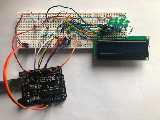
Building a computer form scratch is one of the coolest things you could ever do. Unfortunately doing it, requires a ton of parts that are rarely just siting around.
At least that is what I thought for a long time, but that is actually not true. A lot of common chips can be repurposed to build your own computer.
So today we are going to look at one of the many chips, you can reuse for your computer: the 16*2 LCD.
You can find this chip everywhere, and it just so happens, that this chip has about 80 bytes a ram inside of it. I think you can see where this is going.
The Parts
Here is the parts I used to setup my test.
- 8 resistors ( 1K )
- 11 resistors (10K)
- 8 LEDs
- Lots of wires
- 16*2 LCD (without I2C)
- UNO
- Potentiometer (10K)
Don’t worry if that list looks a bit long. You only need an LCD and a few wires. I used the rest of the parts to speed up the testing process.
The Wiring
Here are the pins on a 16*2 LCD.
| Pin | Use |
|---|---|
| VSS | ground (-) |
| VDD | +5V |
| VO | Contrast Control |
| RS | Register Select |
| RW | Read/Write select |
| E | Enable Pin |
| D0 – D7 | Data pins |
| A (not on all LCDs) | Backlight (+) |
| K (not on all LCDs) | Backlight (-) |
VO, A, and K are all related to how the LCD looks, which is important if you are using the LCD as a display, but when using it for ram, all those pins can be left unconnected. Even so I connected them up, so I could see what the screen was doing.
We will of course need the VSS and VDD pins. Now would be a good time to plug those into the breadboard power rails.
Here is what the rest of the pins do.
The Data pins
Pins D0-D7 are the 8 data pins. We will use these pins to write and read data from the LCD ram. For testing, it is really nice if you have an LED on each of the data pins.
You will also want a pull-down resistor on each pin. Here is the schematic of my setup for a single data pin.

RS
This pin controls if the screen is in Data mode or in Command mode.
| RS | Mode |
|---|---|
| HIGH | Data |
| LOW | Command |
When the LCD is in Data mode, you can read and write data to the ram chip, but you can’t select where you write or read.
In Command mode, you can do a lot of things, but most importantly, you can tell the LCD where you want to write and read data from.
RW
This pin tells the LCD, if you want to read data from it or write data to it.
| RW | Mode |
|---|---|
| HIGH | Read |
| LOW | Write |
E
Whenever this pin goes from LOW to HIGH the LCD checks the current state of the RW and RS pins, and then decides, if it should send data out of the data pins or read data in.
Using The Chip
Now that you know how the pins work, lets see how you can use the chip as RAM.
Writing
Here is how you write data. First, you set the following pins to the correct states.
| Pin | State |
|---|---|
| RS | HIGH |
| RW | LOW |
Once the screen is ready to write, you put an 8-bit binary number on pins D0-D7 with the least significant bit(LSB) at D0.
Lastly, you set the E pin HIGH wait a small amount of time and then set it LOW.
Reading
Reading is very similar to writing. You simply put the following pins into the following states.
| Pin | State |
|---|---|
| RS | HIGH |
| RW | HIGH |
Then, you pull the E pin HIGH, and the data at the current address will be outputted on the data pins, and when you are done reading, you pull the E pin LOW .
Setting the Current Address
When the LCD turns on, the default address is 0, but what if you want a different address.
To set the current address, you start by setting the following pins.
| RS | LOW |
| RW | LOW |
| D7 | HIGH |
Next, you write a 7-bit binary number to pins D0-D6. Because there is only 80 bytes of ram, well there is actually a little more, but it requires a different system to get to, you need to make sure you don’t try to access memory that doesn’t exist for example address 81.
Once you have finished setting the data pins, you trigger the enable pin to make the LCD set the address.
The Address Counter
One thing that is a little unique about this chip is that it has an address counter. After you write or read data to the LCD, the current address gets incremented by one.
Another Use
Besides using these LCDs for RAM, you could also use them as an address counter. After all, I just mentioned they have one built-in.
If you want to use your LCD like this, you will need to know how to read the current address. I am not going to explain how that is done on this page, but you can look at the LCD datasheet to see how it’s done.
If you like learning about how fancy machines work behind the scenes, you might like to look at How to Control a Robot Arm.